Mallory Ignition ACCEL Ignition 35496 User Manual
Page 5
ACCEL IGNITION
www.accel-ignition.com
5
RECOMMENDED TIMING SETTINGS
Street and race advance curve families are shown in Figures 6 and
7. Each family has minimum and maximum curves. The advance slope
switch allows you to run an advance curve in between these minimum and
maximum curves. Advance slope switch setting zero corresponds to the
minimum advance curve. Switch setting 9 corresponds to the maximum
advance curve. Higher switch settings result in a more aggressive curve.
Tuning a particular engine setup always requires some trial and error
experimentation, but maximum power is usually obtained by using the high-
est advance setting possible without audible spark knock. Some recom-
mended starting points are given below:
For stock engines run on normal pump gas (87-89 octane), use the street
advance curves and advance slope setting 5.
For stock or mildly modified engines run on 92 or higher octane gas, use
the street advance curves and advance slope setting 7.
For high compression engines, use the race advance curves and
advance slope setting 2.
You can adjust the initial timing by rotating the ACCEL module relative to
the gear housing (clockwise rotation increases initial timing).
If you experience spark knock only at low RPM, you can try reducing the
initial timing while maintaining an aggressive advance slope for maximum
power at high RPM by increasing the advance slope switch setting. If spark
knock is a problem at high RPM, decrease the advance slope switch setting.
Note that the wide-open throttle (WOT) curves are active unless the
VOES input is grounded. During idle and cruise, the VOES input is grounded
(green VOES LED illuminated) and the low manifold pressure (MAP) curves
are active.
RPM LIMITER SETTING
You can set the RPM limit from 3,000 to 9,900 RPM in 100 RPM incre-
ments by means of two rotary switches. The RPM limit is X100 switch set-
ting (i.e. 57 = 5,700 RPM). Inadvertent settings below 3,000 RPM are ignored
and result in a 3,000 RPM limit.
The Model 35496 uses a newly developed RPM limiting algorithm that
has been highly optimized for odd firing V twin engines. When the engine is
held against the RPM limit, cylinder firing is always paired. This eliminates
a torque couple and results in very smooth operation compared to random
or sequence type RPM limiters.
Set a safe RPM limit that is appropriate for your engine. Most Evolution®
engines with OE valvetrain components should not be run over 5,700 RPM.
STATIC TIMING PROCEDURE
1. Timing marks are located on the flywheel and may be viewed by
unscrewing the inspection hole plug. Most engines will have both TDC
and advance timing marks for the front cylinder as shown in Figure 8. If
you are not sure, refer to your shop manual. You can also identify the
TDC mark by removing the spark plugs and rotating the crankshaft (turn
rear wheel in high gear) until the front piston comes up on TDC.
2. For static timing, you must rotate the crankshaft so that the front piston
is at TDC on the compression stroke. Remove spark plugs and rotate
crankshaft. If you place your thumb over the spark plug hole, you
will feel pressure as the piston comes up on the compression stroke.
Continue rotating the crankshaft until the TDC mark is precisely centered
in the inspection hole.
3. Ground the spark plug cables to avoid a shock hazard. You can use small
jumper wires with alligator clips for this purpose.
4. Turn on the ignition switch. The red LED is used as a timing indicator.
Note that the LED does not immediately illuminate when power is first
turned on. Rotate the ignition unit back and forth until the red LED illumi-
nates. Then slowly rotate the unit clockwise until the LED goes out. Note
that the LED goes out at TDC.
5. Tighten the standoffs to secure the unit. Turn off the ignition switch and
reinstall the spark plugs.
PRECISE TIMING PROCEDURE
1. Use a standard timing light. Note that most dial-back type timing lights
will not work correctly with dual fire applications. If you have a dial-back
timing light, set the dial-back to zero. Do not enable multi-spark while
setting timing.
2. The precise timing procedure is based on using the 35° BTDC timing
mark and race maximum advance curve with VOES grounded that
reaches 35° BTDC around 2,000 RPM (refer to Figure 7). To use this pro-
cedure, you must have a VOES switch connected. If a VOES switch is not
used, you must ground the purple/white wire while setting the timing.
3. Set mode switch to 4 for dual fire or 6 for single fire. Set advance slope
switch to 9. Connect the timing light pickup to the front cylinder spark
plug cable. Loosen standoffs securing the ignition unit. Run the engine
at a steady speed just over 2,000 RPM. Rotate the ignition to center the
35° BTDC timing mark in the inspection hole. Tighten standoffs and verify
that the timing has not changed. When done, change mode and advance
slope switches back to desired values.
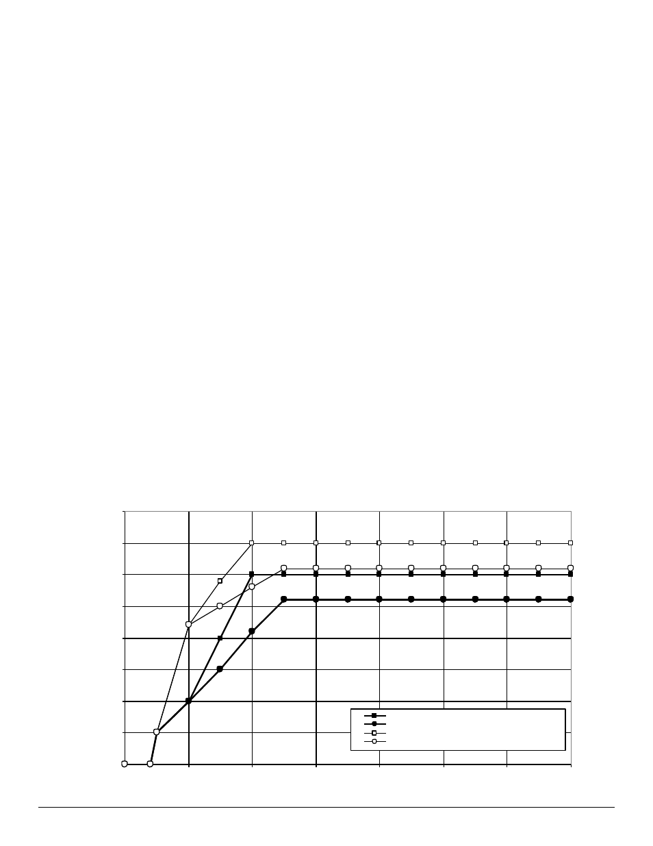
Figure 6 - Street Advance Curves
0
5
10
15
20
25
30
35
40
0
1000
2000
3000
4000
5000
6000
7000
ENGINE RPM
ADV
ANCE
(DE
G
)
MAX ADVANCE AT WIDE OPEN THROTTLE
MIN ADVANCE AT WIDE OPEN THROTTLE
MAX ADVANCE WITH VOES GROUNDED
MIN ADVANCE WITH VOES GROUNDED