Mallory Ignition ACCEL Ignition 35496 User Manual
Page 2
www.accel-ignition.com
ACCEL IGNITION
2
7. Route the wire harness along the frame tubing to the ignition coil.
Make sure that the harness is clear of hot exhaust areas and cannot
chafe against sharp edges. Secure the harness with nylon cable ties.
8. Refer to the appropriate wiring diagram. Use the dual fire hookup
shown in Figure 4 if you have an OE coil or other coil with two primary
terminals. Use the single fire hookup in Figure 5 if you are installing
an aftermarket coil with three primary terminals. Use appropriate
crimp terminals for coil and VOES hookup. With the exception of the
tachometer and rear coil section (single fire only), standard H-D®
wire color codes are used. Tape up any unused wires.
9. Install the supplied Weather Pack connector set on the brown
tachometer wire as shown. If a tachometer is not used, seal the end
of the mating plug with silicone RTV and use it as a protective cover.
Use a proper Weather Pack crimping tool or solder the terminals.
10. Single Fire Tach Hookup. If your motorcycle had a tach before instal-
lation of the ACCEL module, the tach was connected to the pink coil
wire. When you connect the tach direct to the ACCEL module as
shown in Figure 5 for a single fire application, you must make sure
that it is not still connected to the pink coil wire. Trace the wire going
all the way back to the tach to avoid an inadvertent coil connection.
11. Reconnect the battery ground cable. Complete the setup and timing
procedures given on pages 3-7.
12. Reinstall the cover plate using two supplied 10-24 x 1/4” socket head
screws and lock washers in place of the original rivets. You will have
to tap the rivet holes on the inner plate (do this with the plate removed
from the bike to avoid damaging the ignition). You can use the sup-
plied 10-24 x 3/8” self threading screw as a tap.
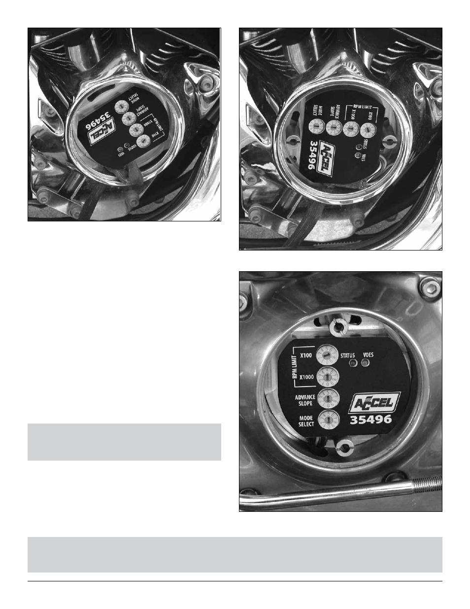
Figure 3B - Finished Sportster® Installation
CAUTION: Engine damage from excessive timing advance may result if the purple/white VOES wire is
inadvertently shorted to ground.
NOTE: The unit is grounded by means of the gear case
housing. The mounting surface must not be anodized or
painted.
Figure 2 - Installing Unit (Note Orientation)
Figure 3A - Finished Big-Twin® Installation