Mallory Ignition ACCEL POINTS ELIMINATOR CONVERSION 2030 User Manual
Page 2
ACCEL POINTS
ELIMINATOR MODULE
ACCEL IGNITION
www.mrgasket.com
2
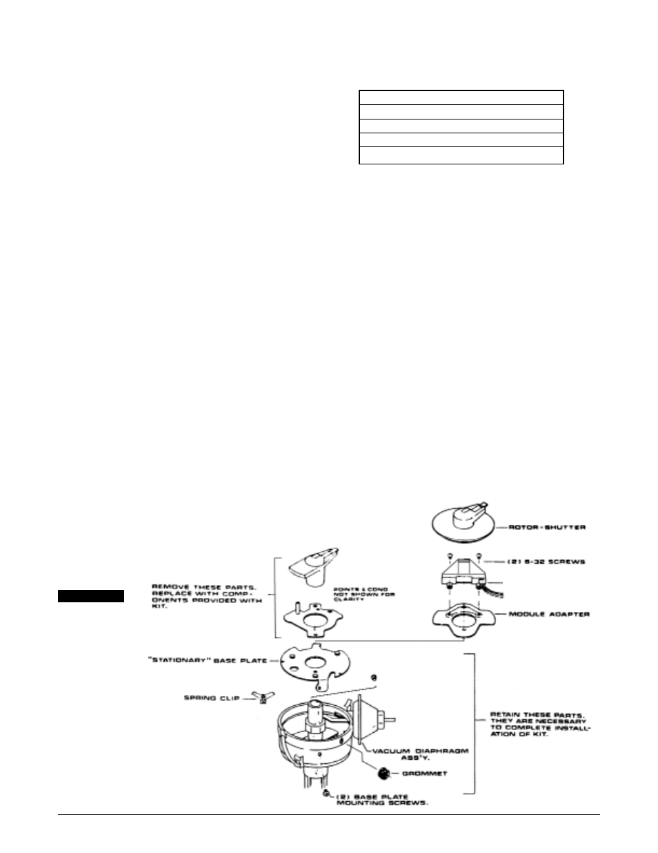
Step 10
Apply a thin coat of white thermal conductive grease to the bottom of
the ACCEL points Eliminator module. Install the ACCEL Points Eliminator
module using the two 6-32 screws supplied.
Step 11
(See Figure2)
Push supplied rubber grommet into hole inside distributor housing. Be
sure flat on flange of rubber grommet is on the outside of the distributor
housing facing upward. Push the three wires from the ACCEL Points
Eliminator Module through rubber grommet, to the outside of the
distributor housing. Mount connector pins into plastic terminal pin
housing supplied. Be sure wires are shoved in to pin housing as shown
in Figure 2. Shove pins into pin housing until a definite click is heard.
GREEN WIRE in hole #1
BROWN WIRE in hole #2
RED WIRE in hole #3
Plug the female connector into the distributor wire harness. See figure #2.
Step 12
Install rotor-shutter onto cam sleeve. Make sure that you press on the
top of the rotor and not the shutter assembly. Be sure it is seated all
the way down onto cam sleeve.
Step 13
If distributor was removed from engine, install back into engine with the
rotor pointing to the same location from which it was originally removed.
Step 14
Install the distributor cap onto distributor housing.
WIRING PROCEDURE
(See Figures 3, 4 and 5)
Step 1
Make sure that your vehicle is equipped with an ignition ballast resistor
(or loom resistance wire) in the wire between the ignition switch and
the coil (+) terminal. If you find your vehicle is not equipped with an
ignition ballast resistor, install an ACCEL Ignition Ballast Resistor Part
No. 150001 in series in the wire from the ignition switch. For optimum
performance in systems without an ACCEL 257+/300+ or similar
ignition control, use one of ACCEL 4 specially matched coils which
eliminates the need for a ballast resistor or a resistance wire. These
coils are: 140305, 8140 or 8140C SuperStock Canister Coil, 140009 HD
E-core SuperCoil.
Step 2
There are three wires coming from the distributor wire harness:
RED WIRE:
Connect to the coil (+) terminal.
GREEN WIRE:
Connect to the coil (–) terminal.
BROWN WIRE:
Connect to engine block ground.
Clean away any grease, oil and paint from the mounting surface before
the connection is made.
NOTE: If an ACCEL 275+/300+ Electronic Ignition Control or any
other aftermarket ignition control is being used, connect the
distributor wire harness according to the instructions supplied
with the ignition control.
ADDITIONAL CONNECTIONS
Tachometer operation: Connect tachometer wire or wires as
recommended by the actual tachometer manufacture.
STARTING THE ENGINE
CAUTION: Be sure all tools, wires and miscellaneous objects are
clear of moving engine parts and extreme heat before starting
the engine.
Recheck all wires and connections to make sure they are correct. Check
and clean, or replace spark plugs. If replacing spark plugs, use types
recommended by the engine manufacturer.
Step 1
Connect a timing light. Find the area with the best view of the timing marks.
Step 2
Start engine. If it fails to start, rotate the distributor in small increments
clockwise or counterclockwise until engine starts. Do not exceed more
than ten degrees of distributor housing rotation in either direction.
Step 3
Set timing as recommended by engine manufacturer, then tighten
distributor hold down clamp. Make sure timing is still correct. If timing
has moved, repeat this procedure.
Step 4
Re-connect the vacuum hose between the vacuum chamber and the
carburetor.
DISTRIBUTOR TUNE–UP PARTS
PART NO.
DISTRIBUTOR CAP
120326
ROTOR – SHUTTER WHEEL
334
ACCEL Points Eliminator Module
2005
DISTRIBUTOR WIRE HARNESS
29349
FIGURE 1