Mallory Ignition ACCEL POINTS ELIMINATOR CONVERSION 2010 User Manual
Page 2
ACCEL IGNITION
www.mrgasket.com
2
Step 12
Install the distributor with the rotor and vacuum chamber pointing in the direction as
noted in Step 5. The rotor must be pointing (approximately) at the mark on the
distributor housing from Step 2.
NOTE: The distributor must be fully seated into the engine. It may be
necessary to turn the oil pump drive, or turn the engine crankshaft two full
turns until the timing mark lines up (again) with the TDC mark on the timing
tab, to allow the distributor to seat fully.
Step 13
Turn the distributor housing until the nearest slot on the shutter wheel is
approximately in the center of the optics of the ACCEL Points Eliminator module. This
will generally give timing close enough for starting purposes. The rotor must be point-
ing (approximately) at the mark on the distributor housing from Step 2. Put the dis-
tributor hold down clamp in place and tighten slightly, leaving it loose enough to turn
the distributor.
Step 14
Install the distributor cap.
WIRING PROCEDURE (See Figures 3, 4 and 5)
Step 1
Make sure that your vehicle is equipped with an ignition ballast resistor (or loom
resistance wire) in the wire between the ignition switch and the coil (+) terminal. If
you find your vehicle is not equipped with an ignition ballast resistor, install an ACCEL
Ignition Ballast Resistor Part No. 150001 in series in the wire from the ignition switch.
For optimum performance in systems without an ACCEL 275+/375+ or similar
ignition control, use one of ACCEL's 4 specially matched coils which eliminates the
need for a ballast resistor or a resistance wire. These coils are: 140108, 8140 or
8140C Canister SuperStock coil, 140009 HD E-core SuperCoil.
Step 2
There are three wires coming from the distributor wire harness:
RED WIRE: Connect to the coil (+) terminal.
GREEN WIRE: Connect to the coil (–) terminal.
BROWN WIRE: Connect to engine block ground.
Clean away any grease, oil and paint from the mounting surface before the
connection is made.
NOTE: If an ACCEL 275+/300+ Electronic Ignition Control or any other
aftermarket ignition control is being used, connect the distributor wire harness
according to the instructions supplied with the ignition control.
STARTING THE ENGINE
CAUTION: Be sure all tools, wires and miscellaneous objects are clear of
moving engine parts and extreme heat before starting the engine.
Recheck all wires and connections to make sure they are correct. Check and clean,
or replace spark plugs. If replacing spark plugs, use types recommended by the
engine manufacturer.
Step 1
Connect a timing light. Find the area with the best view of the timing marks.
Step 2
Start engine. If it fails to start, rotate the distributor in small increments clockwise or
counterclockwise until engine starts. Do not exceed more than ten degrees of
distributor housing rotation in either direction.
Step 3
Set timing as recommended by engine manufacturer, then tighten distributor hold
down clamp. Make sure timing is still correct. If timing has moved, repeat this procedure.
Step 4
Re-connect the vacuum hose between the vacuum chamber and the carburetor.
DISTRIBUTOR TUNE–UP PARTS
PART NO.
DISTRIBUTOR CAP
120214
ROTOR
130117
SHUTTER WHEEL (Two Piece)
338
ACCEL Points Eliminator Module
2005
DISTRIBUTOR WIRE HARNESS
29349
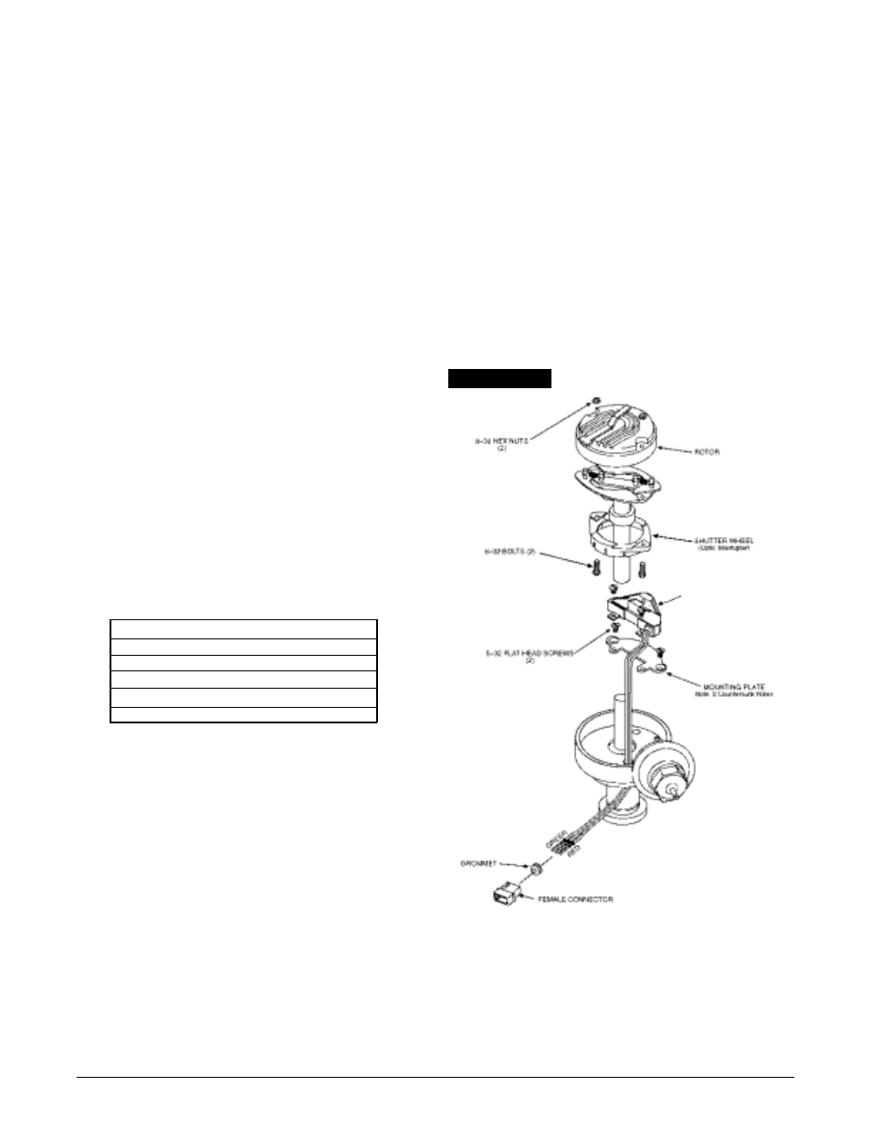
FIGURE 1
ACCEL POINTS
ELIMINATOR MODULE