Calibration, Sensitivity, Calibration factor – Liquid Controls IT200N User Manual
Page 6: Formula 2
Sponsler, Inc.
IT200N Remote Rate Indicator
pg. 6
DOC#: MN-200N-D.DOC
Frequency =
K-Factor x Flowrate
60
CALIBRATION
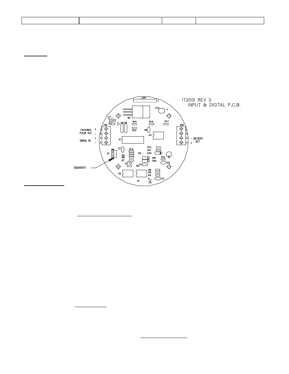
Sensitivity
The sensitivity adjust R1 is located on the IT200I (Input and Digital) P.C.B. The amplitude of the signal
generated by the turbine is proportional to the rate of flow; therefore, sensitivity should be adjusted at
the lowest usable flow rate. Rotate R1 completely counterclockwise then slowly rotate R1 clockwise until
the display correctly responds then increase R1 slightly clockwise. The nominal R1 position is with the
arrow indicating 11 o’clock.
FIGURE 2
Calibration Factor
The calibration factor is derived from the turbine’s K-Factor (Pulses per gallon or other desired
engineering unit).
C.F. =
K-Factor (Gallon)
Engineering Units
EXAMPLE 1: K-Factor = 250 pulses per gallon
Engineering Units = gallons
∴ C.F. = 250/1 = 250
On the Factoring P.C.B.:
Set S1@0, S2@5, S3@2, S4@0, S5@0 (S5 is most significant digit,
∴ CF entered is
00250)
The Calibration Factor is initially loaded @ ‘POWER ON’ or by activating RESET.
The electrical accuracy can be verified by injecting a stable frequency @ TB2-1,2 on the Mounting
P.C.B. and incorporating the following formula:
Rate =
F x 60
C.F.
Where F = Frequency in Hz (
)
Formula 1
Formula 2