Liquid Controls IT200N User Manual
Page 11
Sponsler, Inc.
IT200N Remote Rate Indicator
pg. 11
DOC#: MN-200N-D.DOC
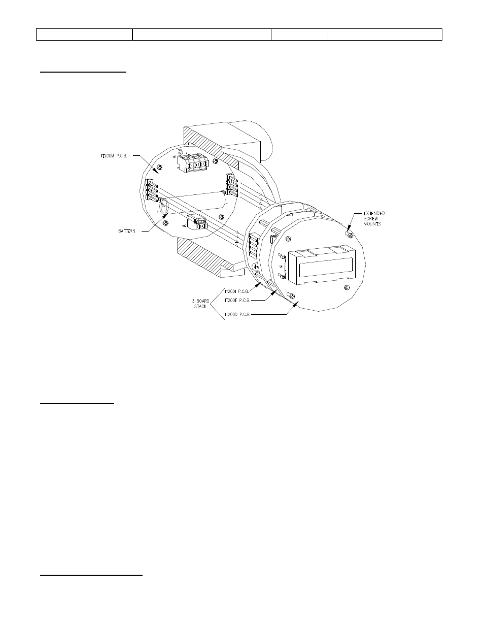
Battery Replacement
The battery is located on the Mounting P.C.B. and inserts into 2 sockets. When installing the battery, it
is imperative to OBSERVE POLARITY. Simply pull the 3-board stack (See Figure #5) out of the
enclosure, install the battery and reinsert the board stack. The display will be all zeros.
FIGURE 5
This figure illustrates the removal of the 3-board stack from the condulet. Note that the mounting board
is not removed.
CAUTION: Do not use the LCD module or S6 as grip points to remove the board stack. Use the
extended screw mounts provided.
To put the 3-board stack back in the condulet, align as illustrated and push down.
% of Flow Display
By incorporating a calibration factor formula the IT200N can be used to display rate of flow as a
percentage
% C.F. = F/S Frequency x 60/100
Example #11: The calibration sheet indicates that the maximum flow rate of an 1 ½” flowmeter is 130
GPM @ a frequency of 500Hz, 65 GPM (50%) = 250 Hz
% C.F. = 500 Hz x 60/100
= 30,000/100
= 300
On the Factoring P.C.B.:
Set S1@0, S2@0, S3@3, S4@0, S5@0
Given 65 GPM = 250 Hz = 50% % = 250 Hz x 60/300 = 50% displayed
Dimensional Information