Calibration ‘0-1’ function, Formula 2 – Liquid Controls IT275N User Manual
Page 7
Sponsler, Inc.
IT275N Remote Totalizer & Rate Indicator
pg. 7
DOC#: MN-275N-A
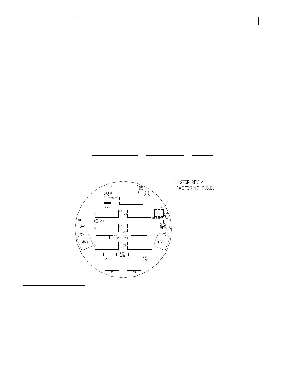
On the IT275F PCB
Set S5@4, S6, 7, 8@0 (.4000)
Set S4 in ‘0’ position (0.4000)
The electrical accuracy can be verified by injecting a stable frequency @ TB2-1,2 on the Mounting PCB
and incorporating the following formula:
Total = F x T x C.F.
D
Where F = Frequency in Hz (Frequency = K-Factor X Flowrate)
60
T = Time (Duration) of test in seconds
C.F. = Calibration Factor as entered in S4-S8
D = Divider as entered in S3
Example 2:
F = 500 Hz T = 1 minute (60 sec) C.F. = .4000
Total Displayed =
500 x 60 x .4000
=
30,000 x .400
=
12000
= 120 in 1 minute
100
100
100
Rate Indicator will display 120 continuously.
FIGURE 3
Calibration ‘0-1’ Function
The ‘0-1’ function provides enhanced accuracy when totalization encompasses a large quantity for an
extended period of time such as SCF produced in a 24-hour period.
The ‘0-1’ function should be incorporated only when both conditions listed below are met:
1) C.F.’s 1
ST
digit right of decimal is 1
2) C.F.’s 5
th
digit right of decimal is not 0
Formula 2