Calibration, Sensitivity, Formula 1 – Liquid Controls IT275N User Manual
Page 6
Sponsler, Inc.
IT275N Remote Totalizer & Rate Indicator
pg. 6
DOC#: MN-275N-A
CALIBRATION
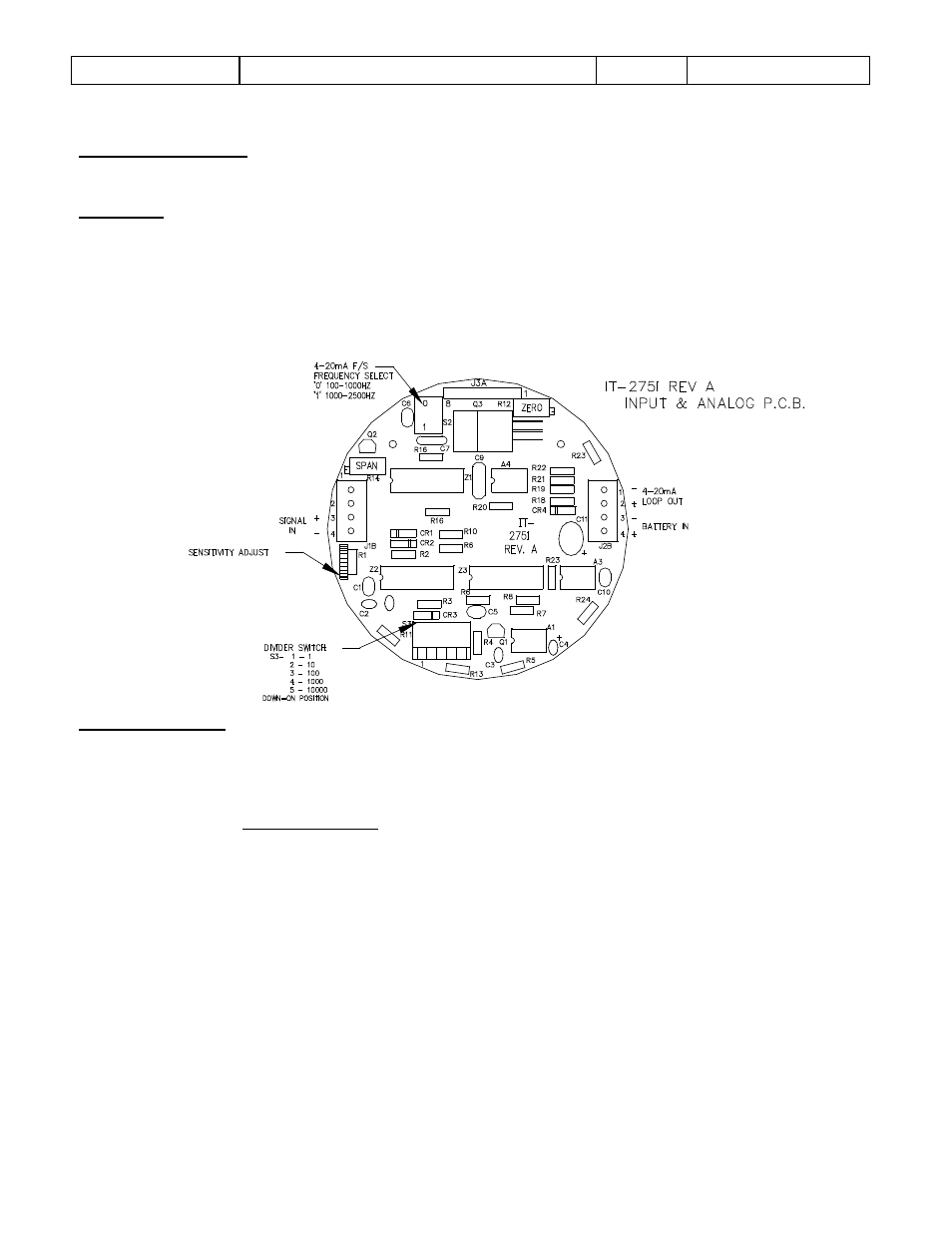
Sensitivity
The sensitivity adjust R1 is located on the IT275I (Input and Analog) PCB. The amplitude of the signal
generated by the turbine is proportional to the rate of flow; therefore, sensitivity should be adjusted at
the lowest usable flow rate. Rotate R1 completely counterclockwise then slowly rotate R1 clockwise until
the display correctly responds then increase R1 slightly clockwise. The nominal R1 position is with the
arrow indicating 11 o’clock.
FIGURE 2
Calibration Factor
The calibration factor is derived from the turbine’s K-Factor (Pulses per gallon or other desired
engineering unit).
C.F. = Engineering Units
K-Factor
The calibration factor is used for total and rate; the desired engineering unit for totalization is also the
engineering unit for displayed rate per minute. 2 different engineering units for total and rate is not
possible.
Example 1:
K-Factor = 250 pulses per gallon
Engineering Units = gallons
∴ C.F. = 1/250 = .004000
On the IT275I PCB:
Set S3 #3 ‘ON’ (
↓ Position) for ÷ 100 (moves decimal point right 2 places)
Formula 1