Installation overview, Mechanical installation, Warning be prepared – Liquid Controls Differential Pressure Transducer User Manual
Page 6
6
Installation Overview
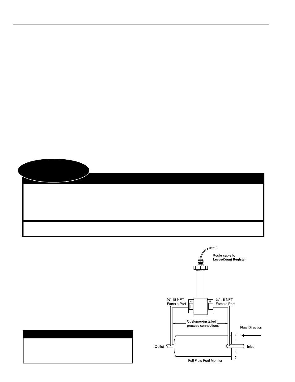
1. Install ΔP transducer and piping between a point immediately upstream and a point immediately downstream of the full flow
fuel monitor or water coalescer.
2. Wire the ΔP transducer to the LectroCount electronic register.
3. Set the shutdown value on the LectroCount LCR-II or LCR 600.
Mechanical Installation
Installation notes
•
The differential pressure transducer has two ¼"-18 NPT female ports. The transducer is shipped with a protective cap on each port.
These protective caps should remain in place until the transducer is ready to be connected to the process lines.
•
The transducer ports are marked with a “+” sign and a “-” sign. This designates the high pressure side and low pressure side,
respectively. Ensure that the transducer is installed in the correct orientation.
•
Ensure that the transducer is installed in a location where it will not be damaged.
•
The transducer is provided with a sixteen foot cable. If longer cable length is required, be sure to use compatible wire not smaller
than 24 gage.
•
Install the transducer with service in mind. Provide ample space for periodic inspection and maintenance.
Never attempt to clean out the transducer ports using
metal objects. Metal diaphragms located in these
ports may become scratched, punctured, deformed, or
damaged as a result.
Handle the transducer Ports with Care
Before disassembly of any meter or accessory component:
• All internal pressures must be relieved and all liquid drained from the system in accordance with
all applicable procedures.
• Pressure must be 0 (zero) psi.
• Close all liquid and vapor lines between the meter and liquid source.
Failure to follow this warning could result in property damage, personal injury, or death from
fire and/or explosion, or other hazards that may be associated with this type of equipment.
!
WarnInG
be Prepared
Safely Evacuate
Piping System
MechanIcal InstallatIon
to install the ∆P transducer:
1. Safely evacuate the piping system.
2. Determine the best location for the differential pressure
transducer and for the customer-installed process
connections to the full flow fuel monitor, water coalescer,
or other device to be monitored.
3. Connect each of the process tubes to the full flow fuel
monitor (or other device to be monitored). The process
tubing must be in compliance with the requirements
of the application. It is recommended that the process
tubing inner diameter should be at least 1/8" and have a
minimum rating of 150 PSI.