Impulse 7201 User Manual
Page 15
Technical Description
Sealevel Systems ULTRA COMM+2.PCI Page
12
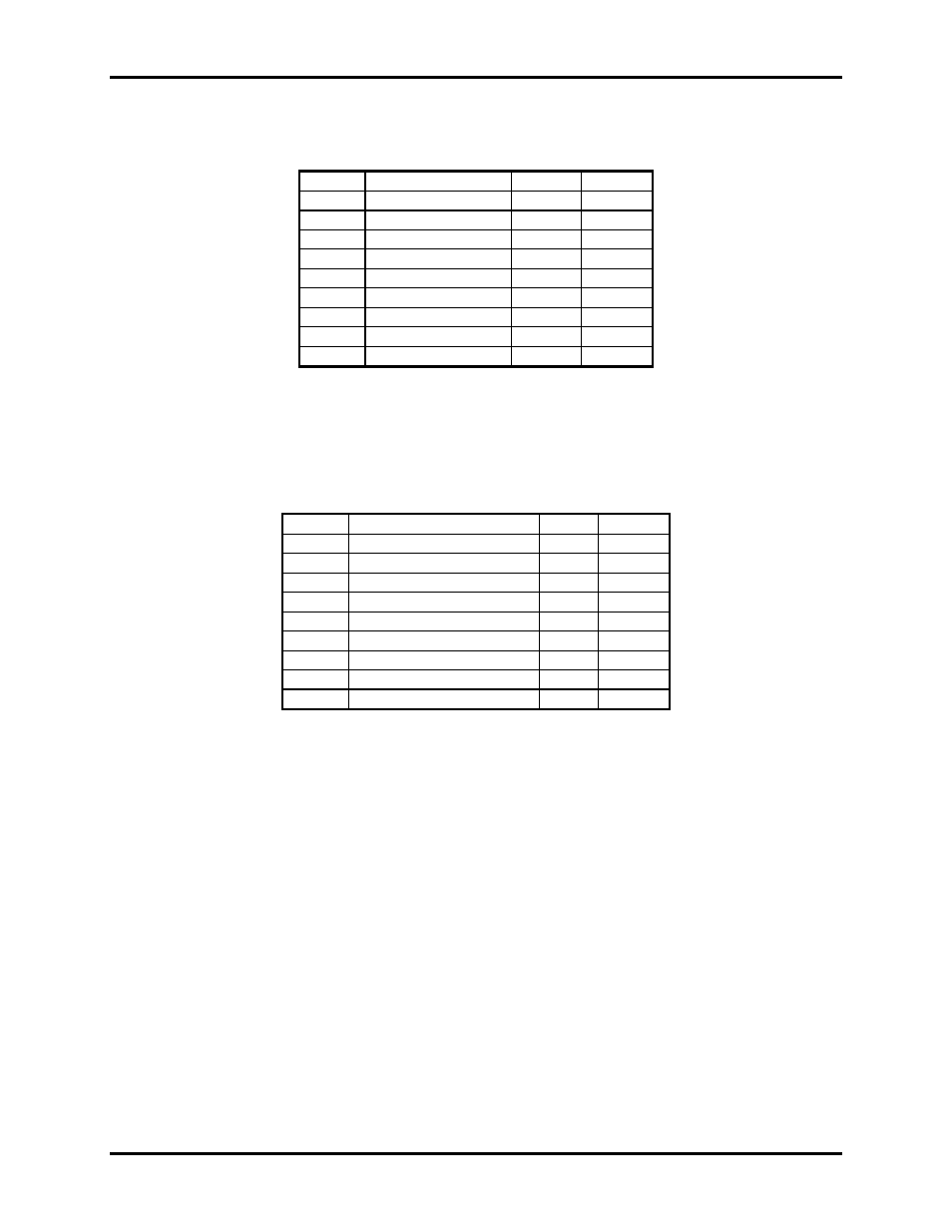
Connector Pin Assignments
RS-232 (DB-9 Male)
Signal Name Pin
#
Mode
TD
Transmit Data
3
Output
RTS
Request To Send
7
Output
DTR
Data Term Ready
4
Output
GND Ground
5
RD
Receive Data
2
Input
DCD
Data Carrier Detect
1
Input
DSR
Data Set Ready
6
Input
CTS
Clear To Send
8
Input
RI Ring
Indicator
9 Input
Note: These assignments meet EIA/TIA/ANSI-574 DTE for DB-9 type connectors.
Technical Note
: Please terminate any control signals that are not going to be used. The most common way to do this is connect RTS to
CTS and RI. Also, connect DCD to DTR and DSR. Terminating these pins, if not used, will help insure you get the best performance from
your adapter.
RS-422/485 (DB-9 Male)
Signal Name Pin
#
Mode
GND Ground
5
TX +
Transmit Data Positive
4
Output
TX-
Transmit Data Negative
3
Output
RTS+
Request To Send Positive
6
Output
RTS-
Request To Send Negative
7
Output
RX+
Receive Data Positive
1
Input
RX-
Receive Data Negative
2
Input
CTS+
Clear To Send Positive
9
Input
CTS-
Clear To Send Negative
8
Input