Hardware configuration, Dipswitch settings, Ipswitch – Impulse 7205e User Manual
Page 5: Ettings
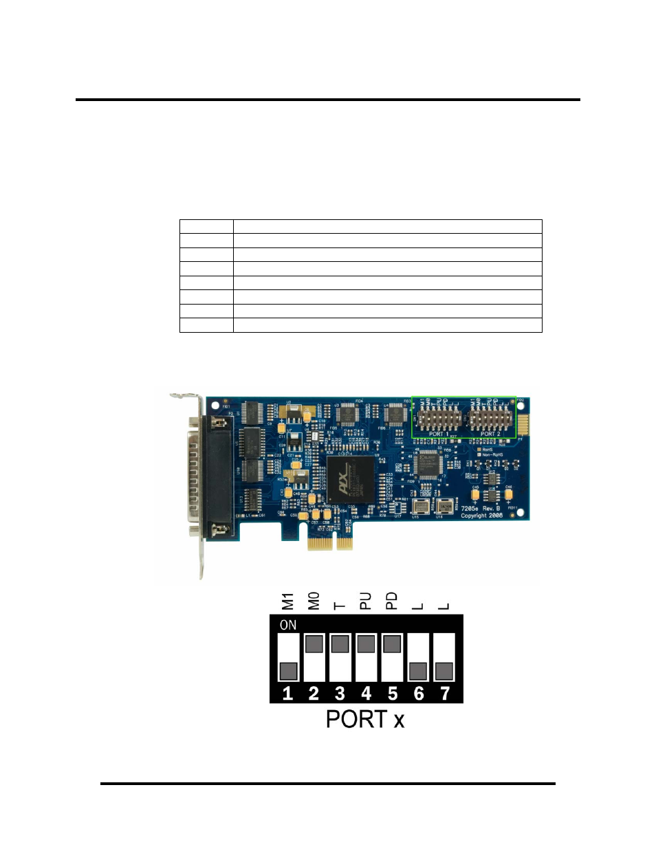
Hardware Configuration
There are two sets of 7-position dipswitches on the board that are used to set the
electrical interface, termination and biasing. The dipswitch located at ‘SW1’ is
labeled ‘PORT 1’ and configures the first serial port. The dipswitch located at
‘SW2’ is labeled ‘PORT 2’ and configures the second serial port. The labels and
description of the function for each switch are detailed in the following table.
Dipswitch Settings
Switch Description
M1
Sets the electrical interface mode (with M0)
M0
Sets the electrical interface mode (with M1)
T
Adds or removes 120 termination
PU
Adds or removes 1K pull-up resistor in RS-422/485 mode
PD
Adds or removes 1K pull-down resistor in RS-422/485 mode
L
Connects TX– to RX– for RS-485 two-wire operation
L
Connects TX+ to RX+ for RS-485 two-wire operation
The location of the dipswitches is outlined in green in the image below. The default
configuration settings are shown in drawing.
© Sealevel Systems, Inc.
- 3 -
COMM+2.LPCIe User Manual