Impulse 3098 User Manual
Page 11
© Sealevel Systems, Inc.
- 9 -
REL-32 User Manual
Jumper Setup Options
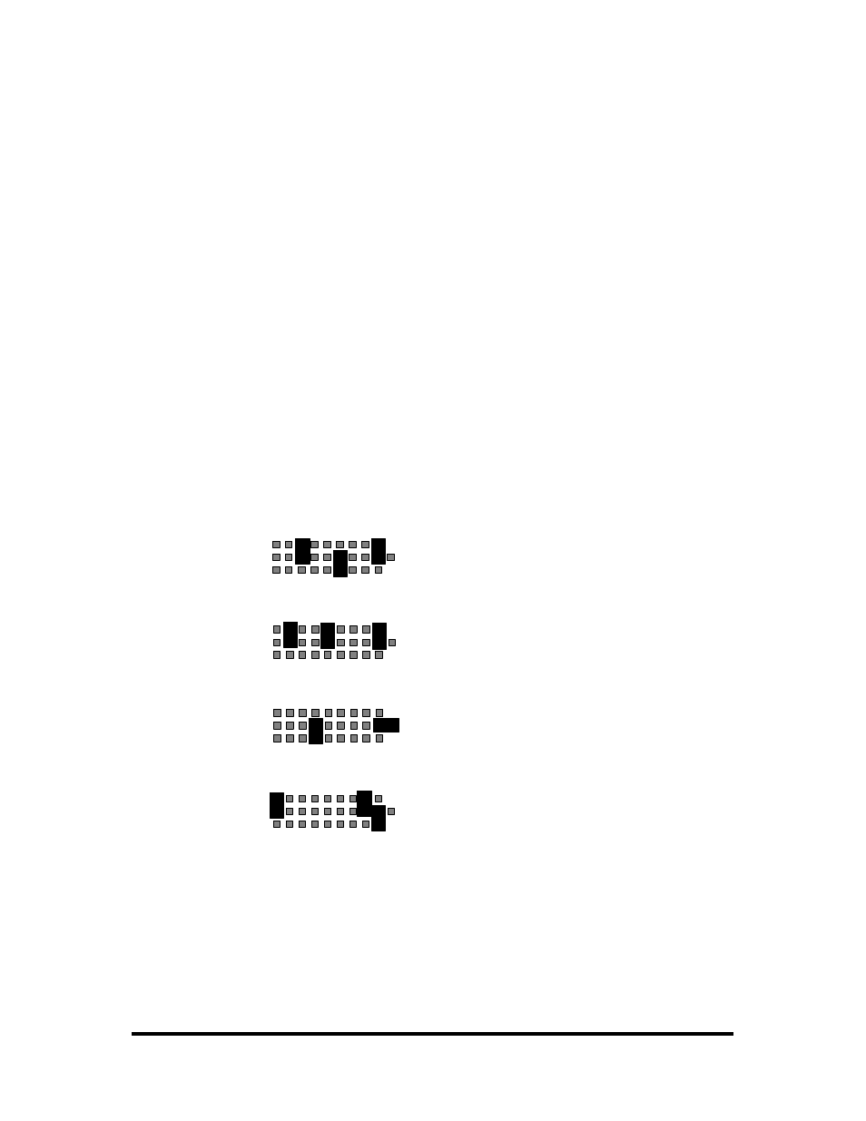
The common on each port may be tied to ground, 5, or 12 volts. Either side of each
relay may then be tied to the common. The 3098 is shipped with all of the jumpers
necessary for all possible configurations. The jumpers are parked on the B-side and
are inactive until configured by the user. An example configuration is shown below:
Port 4: The common is tied to ground (GND).
The A-side of port-4 relay 3 (K27) is tied to the common.
The B-side of port-4 relay 6 (K30) is tied to the common.
Port 3: The common is tied to ground (GND).
The A-side of port-3 relay 2 (K18) is tied to the common.
The A-side of port-3 relay 5 (K21) is tied to the common.
Port 2: The common is tied to 5 volts.
The B-side of port-2 relay 4 (K12) is tied to the common.
Port 1: The common is tied to 12 volts.
The A-side of port-1 relay 1 (K1) is tied to the common.
The A-side of port-1 relay 8 (K8) is tied to the common.
com
A
B
Port 4
GND
5V
12V
1 2 3 4 5 6 7 8
com
A
B
Port 2
GND
5V
12V
1 2 3 4 5 6 7 8
com
A
B
Port 1
GND
5V
12V
1 2 3 4 5 6 7 8
com
A
B
Port 3
GND
5V
12V
1 2 3 4 5 6 7 8