Wiring diagram #4 strobed to serial – Controlled Products Systems Group CVX-1300 User Manual
Page 19
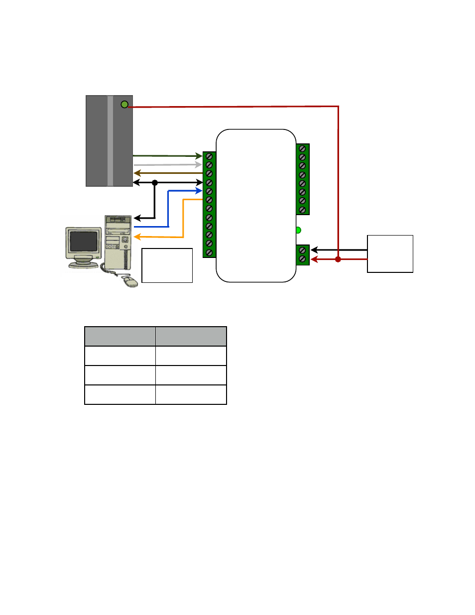
Wiring Diagram #4 Strobed to Serial
The Strobed to RS232 converters support incoming commands to
control the Reader LED and Converter Relay.
RX Data:
NOTE: Commands must be capitalized characters
Turn LED on................
@ L 1
Turn LED off...............
@ L 0
Toggle LED.................
@ L 2
(Bi-Color LED Turns Orange)
Turn Relay on..............
@ R 1
Turn Relay off.............
@ R 0
CVX Terminal
DB9 Pin
Ground
5
RS232 Input
3
RS232 Output
2
DB-9 Connections
Direct to PC Com Port
Reader powered by external supply (8 to 16 VDC)
Connections
to Serial
Device
Card
Reader
D0/Clock In
D1/Data In
LED Out
Ground
RS232 Input
RS232 Output
Ground
+8 to +16 VDC In
Data Bender®
Clock
Strobe
LED
Ground
DC
Power
Supply
(-)
(+)
See also other documents in the category Controlled Products Systems Group Hardware:
- CVT-OPTW (5 pages)
- SPX-5621 (20 pages)
- SPX-5551 (20 pages)
- SPX-5601 (18 pages)
- SPX-7200 (22 pages)
- SPX-7400 (18 pages)
- SPX-7410 (18 pages)
- SPX-7500 (17 pages)
- WDG-5912 (37 pages)
- 030212 (3 pages)
- 108210 (2 pages)
- MC2022 (2 pages)
- 302850 (1 page)
- MVP-1CH-24V-4W-FC (2 pages)
- 298601 (2 pages)
- 300MC (1 page)
- 302210 (4 pages)
- 307010 (2 pages)
- 308301 (2 pages)
- 308302 (2 pages)
- 308913 (2 pages)
- 309013 (1 page)
- 318N (14 pages)
- 355LM (2 pages)
- 414001 (2 pages)
- 420001 (2 pages)
- 466LM (1 page)
- 9921MT (2 pages)
- 9931T (2 pages)
- AM-RRR (2 pages)
- DD (1 page)
- DR-1 (1 page)
- DRA (1 page)
- DT (1 page)
- DT-4A (1 page)
- DTG (2 pages)
- DTKP (1 page)
- G3T-BX (2 pages)
- GITR-3 (2 pages)
- GK-BX (4 pages)
- GLR-BX (1 page)
- GM3T (1 page)
- GRD-2 (1 page)
- MCT-2 (1 page)