Controlled Products Systems Group AM-RRR User Manual
Am-rrr, Remote radio receiver, Installation instructions
AM-RRR
Remote
Radio
Receiver
Installation
Instructions
INTRODUCTION
The AM-RRR remote radio receiver is designed for use with Linear’s AE1000Plus,
AE2000Plus, and AM3Plus access control systems. The AM-RRR functions as
a remote device that extends the radio range control or supplies localized radio
reception for the controller.
Three antenna types can be used with this receiver. The cabinet mounted type
“F” connector is for connection to the antenna. The local whip antenna (supplied)
screws directly on to the receiver’s connector. The directional (EXA-2000) and omni-
directional (EXA-1000) remote antennas wire to the receiver’s antenna connector with
type RG-59 cable.
An on-board RADIO RANGE knob allows adjustment of the receiver’s gain. It can be
set to limit the maximum radio range that the receiver can achieve. Two indicators
display the receivers performance and operation. The two color red/green STATUS
indicator lights red when the receiver is getting DC power and turns green when
access is granted to a transmitter. The RADIO indicator lights when the receiver
detects a radio signal. It can be used for trouble shooting and verifying system
performance. Receiver test points are provided for listening to the incoming signals.
The AM-RRR remote radio receiver connects to the controller control unit through a
six-wire cable. A rotary switch in the AM-RRR selects the PBUS device address for
the receiver. Each PBUS device connected to the controller must be set to a different
PBUS device address. Power is supplied to the receiver from the PBUS controller.
The receiver is housed in a weather-resistant enclosure and can be mounted indoors
or outdoors. Gaskets and a weather-tight wiring strain relief seal the unit from the
elements.
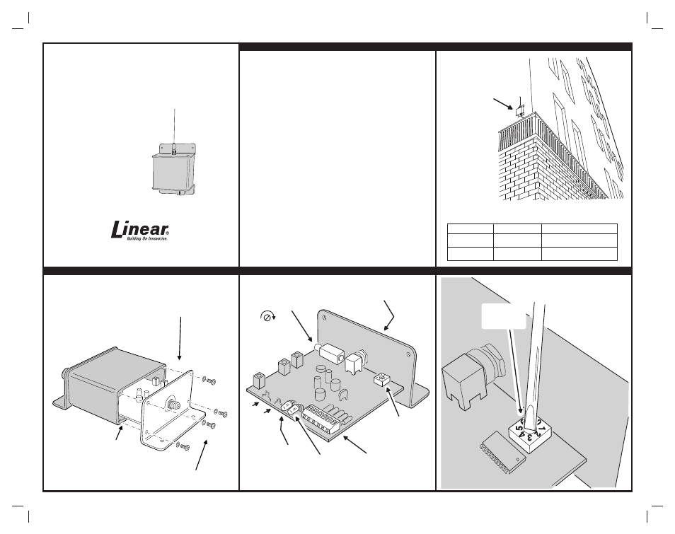
1. TYPICAL INSTALLATION
2. OPEN CASE
3. LOCATE COMPONENTS
4. SET PBUS DEVICE ADDRESS
USA & Canada (800) 421-1587 & (800) 392-0123
(760) 438-7000 - Toll Free FAX (800) 468-1340
www.linearcorp.com
EACH AM-RRR EQUALS 4 LOAD UNITS
CABLE LENGTH FORMULA FOR EACH AM-RRR USED IN SYSTEM
CABLE RUN
CABLE TYPE
FORMULA
300 FEET MAXIMUM
BELDEN 9931 (24 AWG)
WEICO 9405 (20 AWG)
FEET x LOAD UNITS < 3,000 MAXIMUM
FEET x LOAD UNITS < 10,000 MAXIMUM
500 FEET MAXIMUM
AM-RRR MOUNTED
OUTSIDE BUILDING
HOMERUN
WIRE EACH
AM-RRR TO
THE CONTROLLER
OPEN CASE FROM
ANTENNA END
REMOVE FOUR
SCREWS AND WASHERS
BOARD SLIDES OUT
FROM 3RD SLOT UP
INSIDE CASE
RADIO
RANGE
KNOB
CLOCKWISE
FOR MAXIMUM
RANGE
ANTENNA
CONNECTOR
(HIDDEN)
PBUS
DEVICE
ADDRESS
SELECTOR
POWER & DATA
TERMINALS
(CONNECTS TO AM/II)
STATUS
INDICATOR
RED = POWER
GREEN = ACCESS
RADIO
INDICATOR
RADIO
TEST
POINTS
GND
AUDIO
SET TO POSITION 1-6
(MUST BE DIFFERENT
FROM ALL OTHER
PBUS DEVICES)
SET DEVICE
ADDRESS
SELECTOR
PRINTER’S INSTR
UCTIONS:
INSTR, INSTL, AM-RRR- LINEAR P/N:
212045 C - INK:
BLA
CK - MA
TERIAL:
20 LB
. MEAD BOND - SIZE:
11.000”
X 8.500”
- SCALE:
1-1 - SI
DE 1 OF 2