Controlled Products Systems Group SPX-5501 User Manual
Page 9
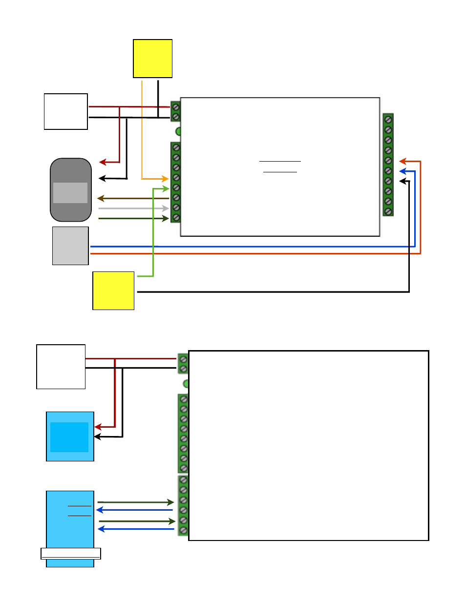
1- Relay 2 N.O.
2- Relay 2 Com
3 - Relay 2 N.C.
4 - Relay 1 N.O.
5 - Relay 1 Com
6 - Relay 1 N.C.
7 - Ground
8 - Aux in
9 - Not used
10 - Not used
1 - 8 to 16 VDC In
2 - Ground
Status LED
1 - exp (+)
2 - exp (-)
3 - +5 VDC out
4 - R4
5 - R3
6 - LED out
7 - D1/Data In
8 - D0/Clk In
SPX-5000
Remote
Card
Reader
DC
Power
Supply
Gate/
Door
Strike
Door
N.C.
Contact
Request
to Exit
1K
1K
Access
Control
Panel
1 - 8 to 24 VDC In
2 - Ground
SPX-6000 Series Central
DC
Power
Supply
1 - +5 VDC out
2 - IN 2
3 - Not Used
4 - N.C.
5 - COM
6 - N.O.
7 - Ground
8 - Ground
1- Not Used
2- Not Used
3 - (-) RS-485
4 - (+) RS-485
5 - RS-232 TX
6 - RS-232 TX
TXD
RXD
-
RS-485
+
RS-485
Computer / PLC