3 bi-parting gates wiring - dual gate operators, Secondary operator terminal, Primary operator control board – Controlled Products Systems Group 6050-080 User Manual
Page 19: Interconnection cable wiring, Primary operator secondary operator, Conduit, Operator chassis ground, Ac power conduit to primary operator only
6050-065-X-7-13
17
Primary Operator’s
2340 Convenience Open
Circuit Board
Gray
(On select models)
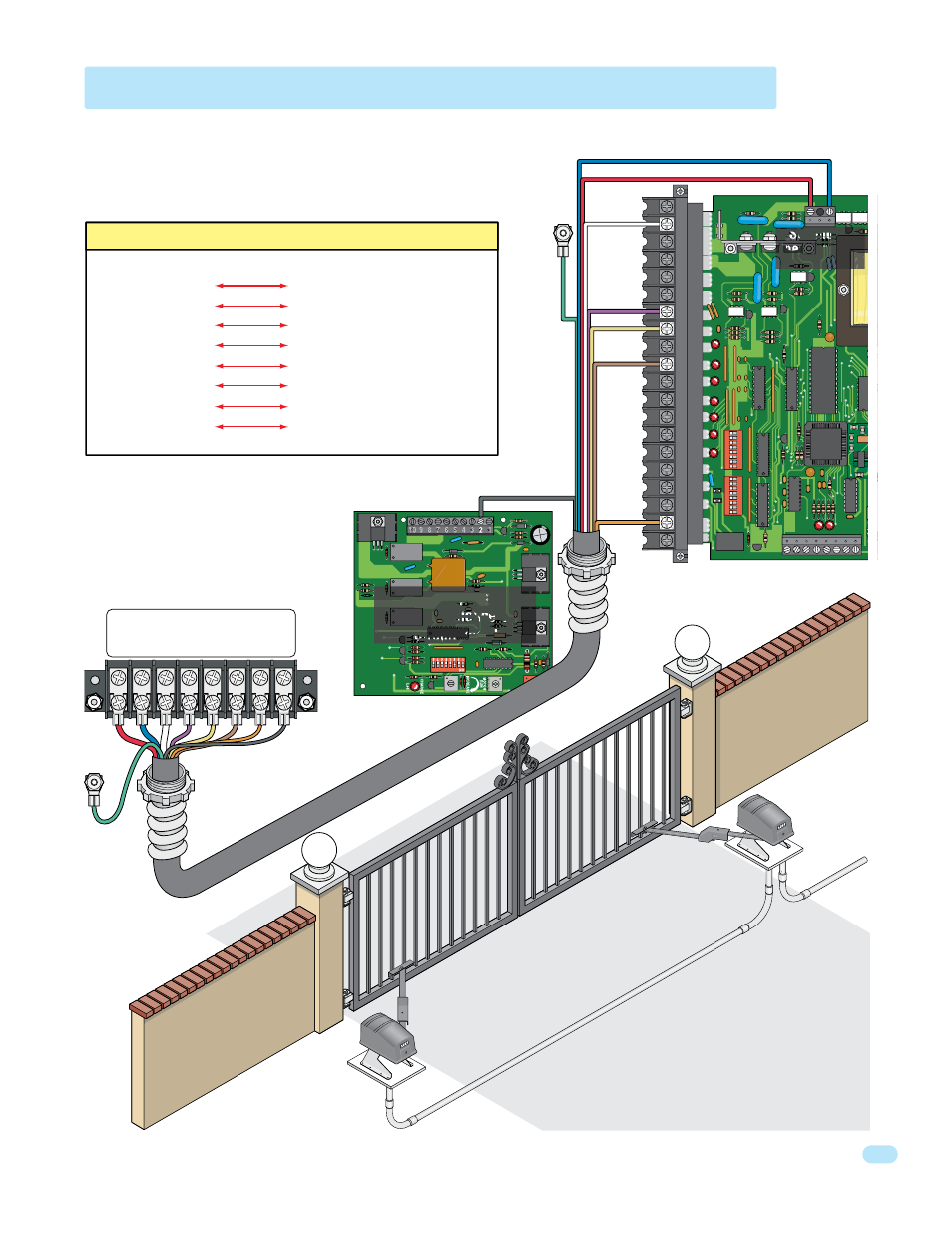
2.3 Bi-Parting Gates Wiring - Dual Gate Operators
1. RED
115 V
AC Motor
2. BLUE
115 V
AC Motor
3. WHITE
115 V
AC Neutral
4. PURPLE
24 V
A
C
5. YELLOW
12 V
A
C
6. BROWN
Pulse 2
7. ORANGE
Common
8
. GRA
Y
Conv Open Input
Conduit
Secondary Operator
Terminal
Conduit
Primary Operator
Control Board
•
All control, loop detector, safety and auxiliary
devices are wired to the primary operator.
•
Secondary operator contains
NO 4502 control board.
Operator
Chassis
Ground
(Green)
Operator
Chassis
Ground
(Green)
Primary
Operator
Secondary
Operator
20
19
18
17
16
15
14
13
12
11
10
9
8
7
6
5
4
3
2
1
NC
NO
PO
1
ON
2
3
4
5
6
7
8
1
ON
2
3
4
5
6
7
8
Connect the Primary/Secondary operators together with DoorKing’s interconnection cable as shown (Different lengths sold separately
P/N 2600-75x). High voltage power and low voltage communications are supplied to the secondary operator by DoorKing’s UL approved cable
that is run in a single conduit. Two conduits (High voltage and low voltage) will need to
be provided to the secondary operator when NOT using DoorKing’s UL listed, wet
environment interconnection cable.
Red
Blue
White
Purple
Yellow
Brown
Orange
Secondary
Operator Motor
Terminal
4502
DoorKing’
s UL Listed (W
et Environment) Primar
y/Secondar
y Interconnection Cable
Primar
y/secondar
y
inter
connection cabl
e
in underground conduit.
AC Power
AC power
conduit to
primary
operator only.
Optional 3.3 Amp Heater Installation Note:
If the optional heaters are to be installed on the
operators, run two (AWG 16-600 volt insulation)
power wires through the interconnection cable conduit to
power the secondary operator’s heater. Refer to the instruction
sheet with the heater kit (P/N 1601-154) for more information.
Primary Operator
Secondary Operator
Interconnection Cable Wiring
Main T
erminal
Motor Terminal #1 (Red)
Motor Terminal #2 (Blue)
Main Terminal Neutral #2 (White)
Main Terminal 24 VAC #7 (Purple)
Main Terminal 12 VAC #8 (Yellow)
Main Terminal Pulse 2 #10 (Brown)
Main Terminal COM #19 (Orange)
2340 Terminal COM #2 (Gray)
For Convenience Open Models
(Red) Motor #1
(Blue) Motor #2
(White) Neutral #3
(Purple) 24 VAC #4
(Yellow) 12 VAC #5
(Brown) Pulse 2 #6
(Orange) COM #7
(Gray) #8
Conv Open Input