Opening to the outside” installation, Closed position open position, Support bar – Controlled Products Systems Group 6003-080 User Manual
Page 13: Rear bracket fabrication, Bottom middle top, Attaching brackets to surfaces
6003-065-Q-2-12
11
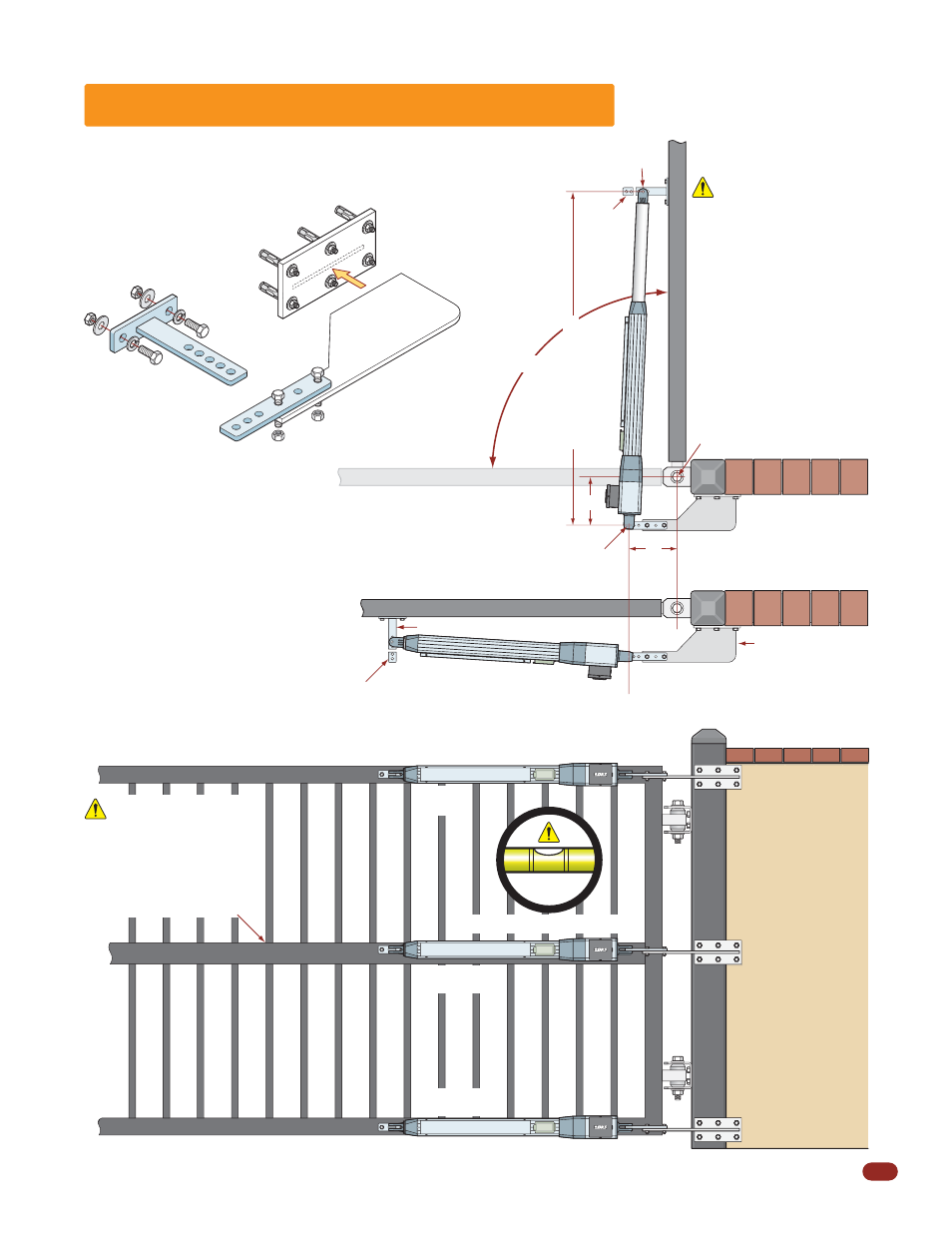
“Opening to the Outside” Installation
7”
Addition to
support bracket
must be
fabricated to
reach wall.
Gate Hinge Pivot Point
Front Bracket
Pivot Point
Gate in Closed Position
Rear Bracket Pivot Point
Closed Position
Open Position
Actuator arm MUST be level!
A support bar must span
the entire length of the
gate to support the gate
pickets. The pickets will
bend if not supported.
Support Bar
90°
7”
Rear Bracket
Do not install the
actuator in fully
extended (Bottomed out)
position. This will
damage the arm. See
next page to prevent this
from happening.
Hardware
(Not Supplied)
Front Bracket
Bolt or weld to gate.
Bolt rear support bracket
to fabricated steel plate
with supplied lock nuts.
Rear Support
Bracket
(Supplied)
Fabricated
Steel Plate
(Not Supplied)
Front Bracket
Cut Off
Excess
Bracket
Cut Off
Excess
Bracket
A rear bracket will need to be fabricated.
The bracket will vary in size depending on
the gate hinge inset. It can be attached to
the wall by welding or bolting, depending
on the type support post/wall.
The bracket MUST be level and VERY
secure to the wall.
Extreme force will
be exerted on this bracket during gate
cycling.
Rear Bracket Fabrication
Bottom Installation
Note: Make sure
that the operator is
mounted high
enough off the
ground that it will
NOT come in
contact with
standing or flowing
water. This will
damage the
operator.
Bottom
Middle
Top
Weld directly to support post
OR reinforcing steel plate
Support Post
Reinforcing steel plate
for sleeve anchors
if desired.
(Not Supplied)
47.5” Open Position
Note: The brackets must be perpendicular (Plumb) to
the gate and wall/post and horizontally level. If welding
brackets to surfaces, weld completely around brackets.
Attaching Brackets to Surfaces
Bolt or weld brackets to gate and support post/wall.