Opening to the inside” installation, Attaching brackets to surfaces, Closed position open position – Controlled Products Systems Group 6003-080 User Manual
Page 12: Support bar, Bottom middle top
6003-065-Q-2-12
10
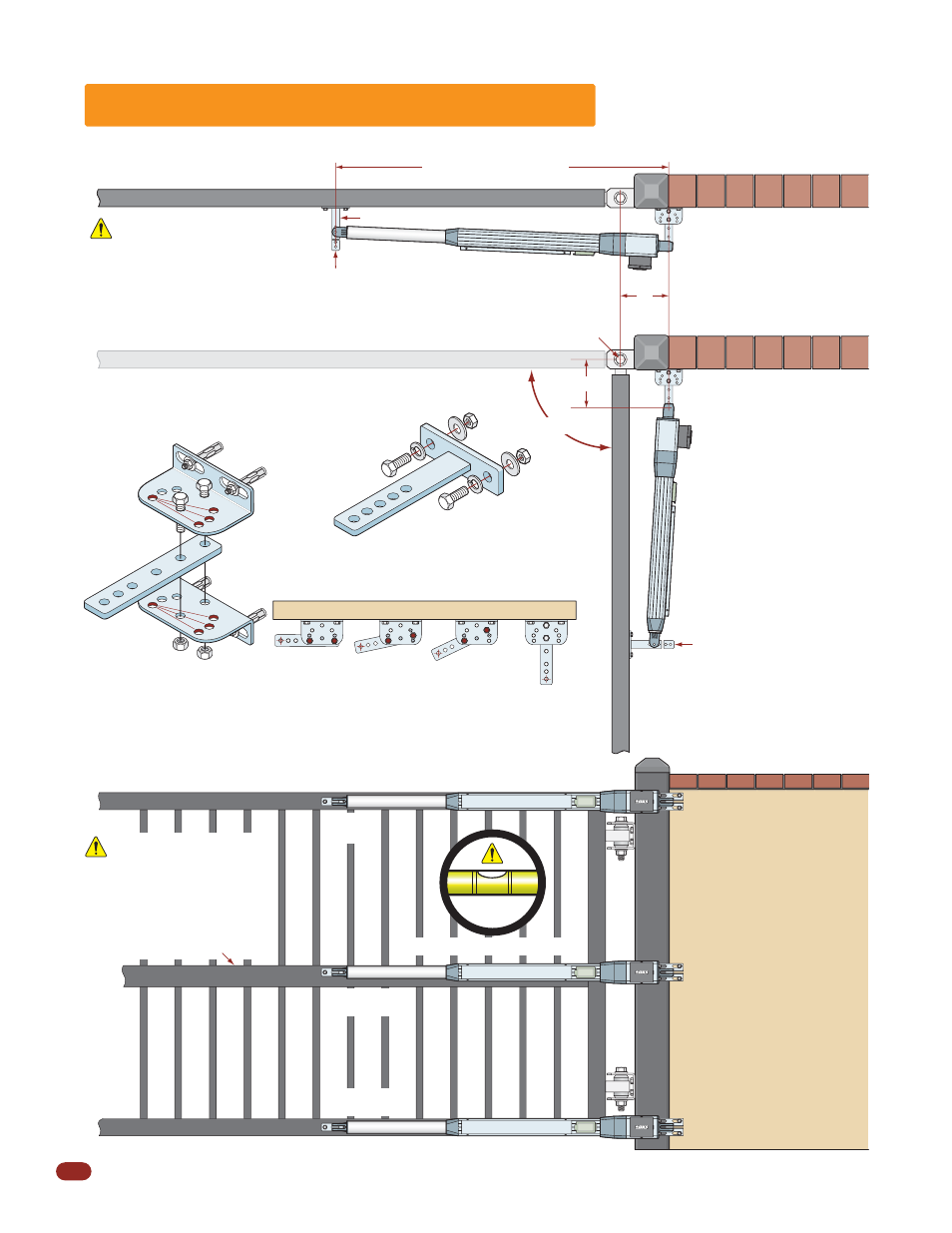
“Opening to the Inside” Installation
47.5” Closed Position
7”
7”
90°
Gate Hinge Pivot Point
Front Bracket Pivot Point
Front Bracket
Rear Bracket Pivot Point
Attaching Brackets to Surfaces
Bolt or weld brackets to gate and support post/wall.
Closed Position
Open Position
Actuator arm MUST be level!
A support bar must span
the entire length of the
gate to support the gate
pickets. The pickets will
bend if not supported.
Support Bar
Gate in Closed Position
Do not install the actuator in
fully extended (Bottomed out)
position. This will damage the
arm. See page 12 to prevent
this from happening.
Hardware
(Not Supplied)
Front Bracket
Bolt or weld to gate.
Angles will reduce operators
distance from wall. See page 12.
Angled Configurations
Wall
2”
2
1/2
”
5
1/2
”
3”
Straight
Rear Bracket Options
Assemble straight out (shown)
or 3 different angles.
Sleeve Anchors
(Not Supplied)
Cut Off
Excess
Bracket
Cut Off
Excess
Bracket
Bottom Installation Note:
Make sure that the
operator is mounted high
enough off the ground
that it will NOT come in
contact with standing or
flowing water. This will
damage the operator.
Bottom
Middle
Top
Support Post
Note: The brackets must be perpendicular (Plumb) to the gate and wall/post and
horizontally level. If welding brackets to surfaces, weld completely around brackets.