Controlled Products Systems Group 109773 User Manual
Page 4
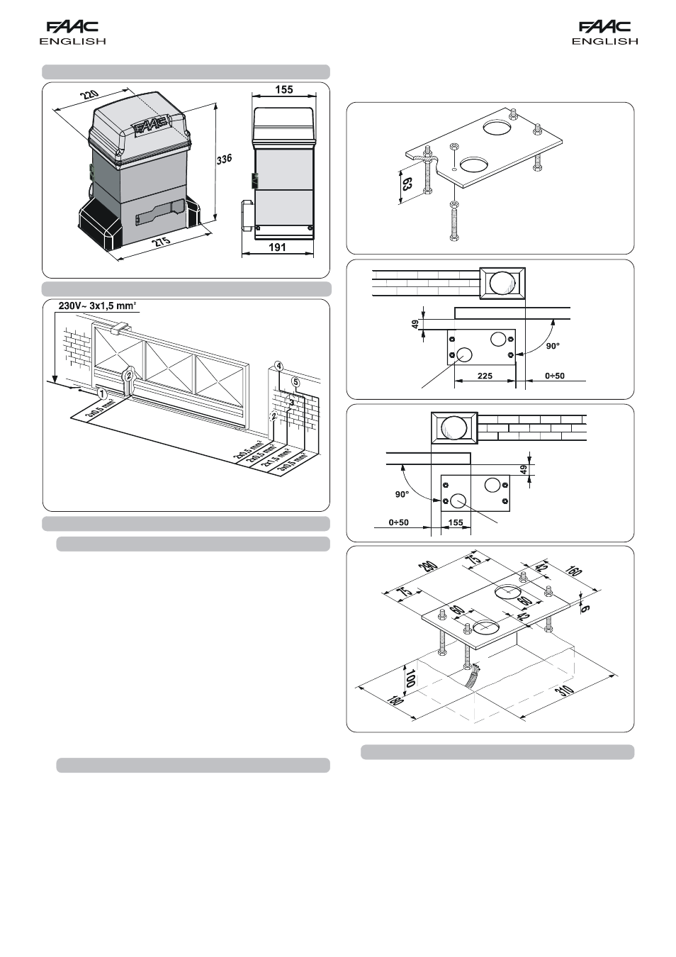
20
Fig. 4
Fig. 5
Fig. 6
Fig. 7
Fig. 2
Fig. 3
2. DIMENSIONS
3. ELECTRIC EQUIPMENT (standard system)
To make the connections efficiently, allow the cables to
project by about 40 cm from the hole (Figs.5-6 ref.
³) of the
foundation plate.
4. INSTALLATION OF THE AUTOMATED SYSTEM
4.1.
PRELIMINARY CHECKS
To ensure safety and an efficiently operating automated system,
make sure the following conditions are observed:
•
The gate structure must be suitable for automation. The following
are necessary in particular: wheel diameter must be in proportion
to the weight of the gate to be automated, an upper guide must
be provided, plus mechanical stop limits to prevent the gate
derailing.
•
The soil must permit sufficient stability for the foundation plinth.
•
There must be no pipes or electric cables in the plinth excavation
area.
•
If the gearmotor is exposed to passing vehicles, install, if possible,
adequate means of protection against accidental impact.
•
Check if an efficient earthing is available for connection to the
gearmotor.
4.2.
MASONRY FOR FOUNDATION PLATE
1) Assemble the foundation plate as shown in figure 4.
2) The foundation plate must be located as shown in figure 5 (right
closing) or figure 6 (left closing) to ensure the rack and pinion
mesh correctly.
3) Prepare a foundation plinth as shown in fig.7 and wall the
foundation plate, supplying one or more sheaths for routing
electric cables. Using a spirit level, check if the plate is perfectly
level. Wait for the cement to set.
4) Lay the electric cables for connection to the accessories and
power supply as shown in figure 3.
4.3.
MECHANICAL INSTALLATION
1) Assemble the securing corners and anti-vibration spacers on
the operator as shown in Fig. 8.
2) Open the cover, unscrewing the securing screws.
3) Place the operator on the plate, using the supplied washers and
nuts as shown in Fig. 9.
During this operation, route the cables through the duct inside
the lower half-casing of the operator (Fig.10 - Ref. A).
To access the electronic equipment, route the cables through
the appropriate hole, using the supplied rubber cable-clamp.
Make absolutely sure to unsheathe all the cables so that the
clamp holds single cables only (Fig.10 - Ref. B).
³
³
ቢ
Operator 746
with 780D equipment
ባ
Photocells
ቤ
Key-operated push-button
ብ
Flashing lamp
ቦ
Radio receiver