Controlled Products Systems Group 109773 User Manual
Page 15
31
M
Fig. 46
Fig. 45
Fig. 44
Fig. 43
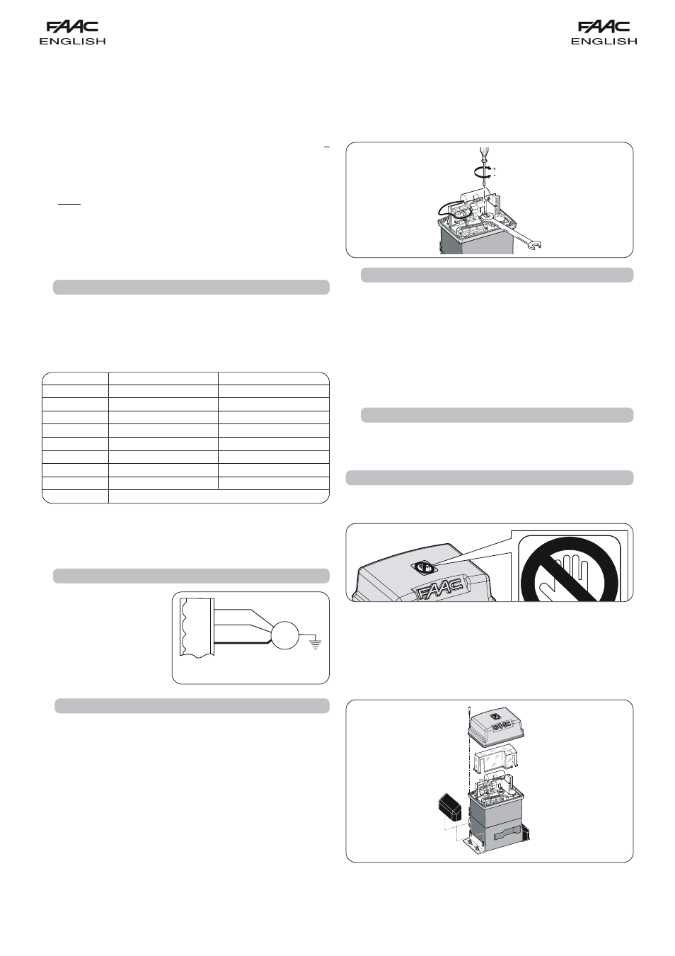
7. FINAL OPERATIONS
At end of installation, apply the danger sticker on the top of
the cover (Fig. 45).
6.7.
CHECK OF STOP POINTS
Take care over the setting of the post-limit-switch deceleration
and braking: If deceleration is too long and braking is insufficient,
the reference fitted on the gate's rack (magnet or steel plate)
can overtake the sensor until the latter is disengaged. When
the gate stops, check if only the limit-switch involved is engaged.
The relevant LED must be OFF - if it went OFF and then ON
again, or if both the limit-switch LEDS are OFF, you must reduce
the post-limit-switch deceleration value and/or increase
braking value (see par.5.5.2).
6.8.
SAFETY DEVICES AND ACCESSORIES CHECK
Check correct operation of all the safety and anti-crushing
devices (ENCODER sensor), and of the accessories used on the
system.
Snap-fit the side panels, fit the equipment's cover and fit the
cover with the supplied screws (Fig. 46).
Remove the vent stop screw (fig. 47).
Hand the "User's Guide" to the Customer, explain correct
operation and use of the gearmotor, and indicate the
potentially dangerous areas of the automated system.
Notes on plate positioning
•
To ensure correct operation, allow at least 2 cm from the
mechanical stop limit in the gate stop position. Carry out this
check after determining the values of the pre- and post-limit
switch decelerations (see par. 5.5.2.) and after running at least
one complete cycle of the automated system.
•
The distance between the limit-switch and the plates must be <
5mm.
•
For nylon racks, use the plate only (without support), securing it
directly to the rack by the self-tapping screws. Make the above
mentioned adjustments.
Note: a steel core is situated 5 mm under the surface of the
nylon rack. Therefore, drill until you reach the steel core and
screw with the self-tapping screws.
6.5.
CHECK OF MOTOR CONNECTION
Check if the motor wiring
is as shown in Fig. 43 (stan-
dard connection).
LEDS
LIGHTED
OFF
OP-A
Command activated
Command inactive
OP-B
Command activated
Command inactive
FC1
Limit-switch free
Limit-switch engaged
FC2
Limit-switch free
Limit-switch engaged
FSW OP
Safety devices disengaged
Safety devices engaged
FSW CL
Safety devices disengaged
Safety devices engaged
STOP
Command inactive
Command activated
SAFE
Safety devices disengaged
Safety devices engaged
ENC
Flashes while the motor rotates
NB.: The status of the LEDs while the gate is closed at rest are shown in bold.
If opening direction is leftward, the status of LEDS FC1 and FC2 is reversed.
6.4.
CHECK OF INPUTS
The table below shows the status of the LEDs in relation to to the
status of the inputs.
Note the following:
L
ED
LIGHTED
= closed contact
L
ED
OFF
= open contact
Check the status of the LEDs as per Table.
Tab. 2 Operation of the signalling status LEDs
BROWN
BLACK
BLUE
J6
MOT 2
MOT 1
MOT
COM
6.6.
ADJUSTMENT OF MECHANICAL CLUTCH
In addition to its electronic safety devices (encoder and force
adjustment), the 746 operator is also equipped with a mechanical
clutch.
For gate force and the encoder, please consult paragraphs 5.5.1
and 5.5.2.
Procedure for adjusting the operating threshold of the mechanical
clutch (you are recommend to set it to conform with current
regulations):
1)
Cut electrical power to the automated system.
2)
Keep the motor shaft locked with a wrench and turn the clutch
adjustment screw with an Allen wrench or screwdriver as shown
in Fig. 44.
To increase torque, turn the screw clockwise.
To reduce torque, turn the screw anti-clockwise.
Ü The operator is supplied with the clutch set to maximum level.
Therefore, you must initially turn the screw anti-clockwise to
reach the best setting.
3)
Power up the automated system and check that the torque you
have just set is correct.