Controlled Products Systems Group 10441811 User Manual
Page 8
Guidelines for Determining Installation Dimensions
• For
90° leaf openings: A+B=L
• For leaf openings
exceeding 90°: A+B
• Smaller A and B dimensions provide higher periph-
eral leaf speed.
• Limit the difference between A and B dimensions to
less than 1.5 inches. Greater differences may cause
speed variations during gate opening and closing
movements.
• Maintain a Z dimension that ensures that the operator
does not strike the pillar.
• In LS models, limit switches are triggered during the
first and last
1.25 inches of gate travel. Therefore
select
A and B dimensions that utilize the entire opera-
tor travel. Short travel ranges can restrict or cancel the
limit switch adjustment range.
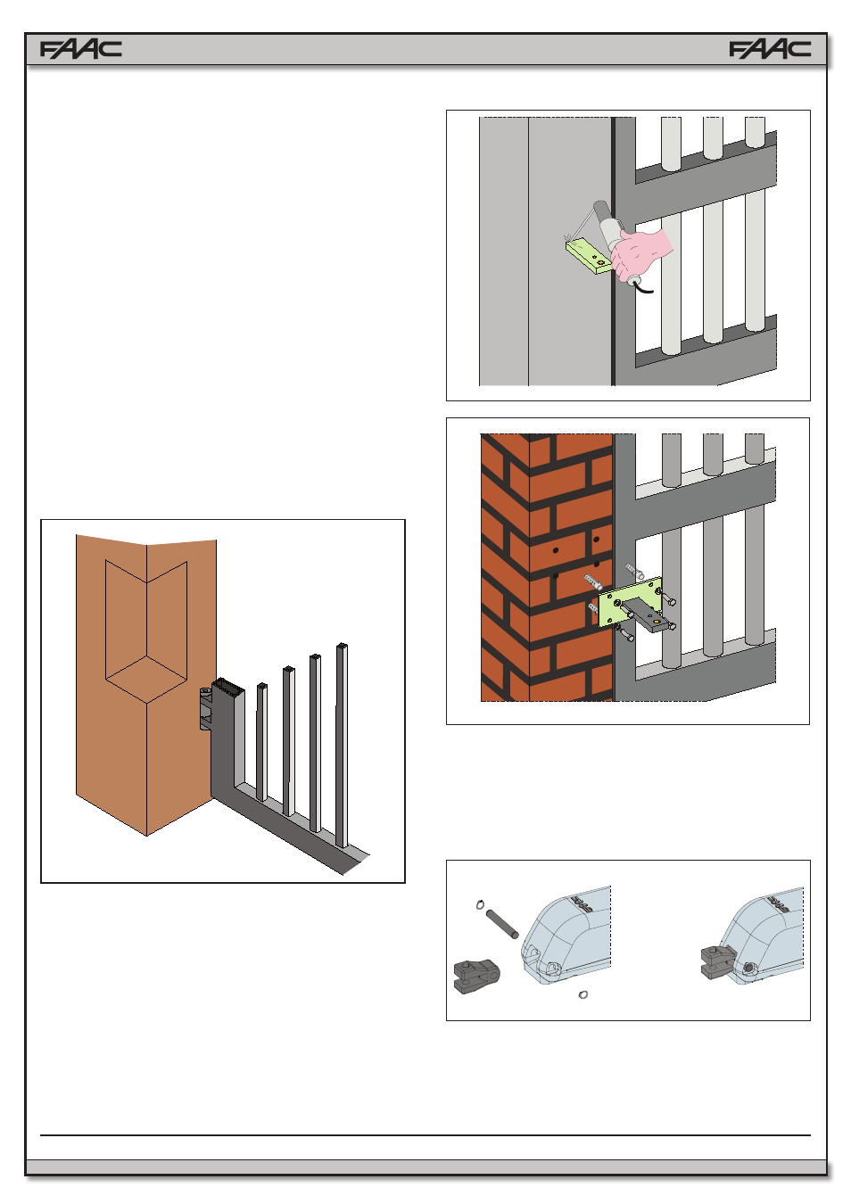
If pillar dimensions or hinge position do not allow installa-
tion of the operator, cut a niche into the pillar (as shown in
Fig. 5) in order to maintain the
A dimension as determined.
The dimensions of the niche should enable easy installa-
tion, rotation and operation of the release device.
4.4. Installing the Operator
1. Fix the rear bracket in the position you previously deter-
mined in Section 4.3.1.
• For iron pillars, carefully weld the bracket directly onto
the pillar (Fig. 6).
• For masonry pillars, use a suitable plate (optional) for
which to attach the unit (Fig. 7). Make use of a suitable
fastening system. Then carefully weld the bracket to the
plate.
While fastening the bracket, use a level to ensure that it
is perfectly horizontal.
2. Assemble and attach the rear fitting to the operator (Fig.
8).
3. Set the 415 Operator to manual operation (see Section 6).
4. Completely extend the rod until it reaches the limit stop
(Fig. 9, Ref. 1).
5. Re-lock the operator (see Section 6.1).
8
FAAC Model 415 L LS 24V Swing Gate Operator
Fig. 5
Fig. 7
Fig. 6
Fig. 8