Technical specifications 4. installation – Controlled Products Systems Group 10441811 User Manual
Page 7
3.
TECHNICAL SPECIFICATIONS
4. INSTALLATION
Pos. Description
Cables
1
Operators
2 x AWG 14 (max 30’)
AWG 12 (max 50’)
AWG 10 (max 100’)
1
Limit Switches
3 x AWG 20
2
Control Unit
3 x AWG 14
(AC power)
3
TX Photocells
4 x AWG 20
4
RX Photocells
2 x AWG 20
5
Key-operated Switch
2 x AWG 20
6
Flashing Lamp
2 x AWG 14
7
Receiver
3 x AWG 20
8
Mechanical Stops
-
SPECIFICATION
415 L LS 24V
Power Supply
24 VDC
Power (W)
70
Current (A)
3
Thrust (lbf)
630
Effective Stroke (inches)
15
Rod Extension Speed (inches/sec)
0.5
Max Leaf Length (feet)
15
Cycle per hour at 68˚F (approx)
75
Class or Operation
Residential
Ambient Operating Temperature
Range (˚F)
-4 to +131
Operator Weight (lbs)
17.5
Protection Class
IP 54
4.2 Preliminary Checks
The condition of the gate structure directly affects the reliabil-
ity and safety of the automated system. Before installing the
415 Operator, prepare the gate for the operator by performing
the following:
• Make sure that the gate structure is solidly built. Add rein-
forcing crosspieces to the gate leaves if necessary.
• Make sure that the gate moves smoothly on its hinges
without excessive friction by swinging it opened and
closed by hand. If necessary, lubricate all the gate’s
moving parts.
Positive stops are not needed with the 415 operator, the built
limit switches can be used to limit the rod travel
4.1 Electrical Set-up (Standard System)
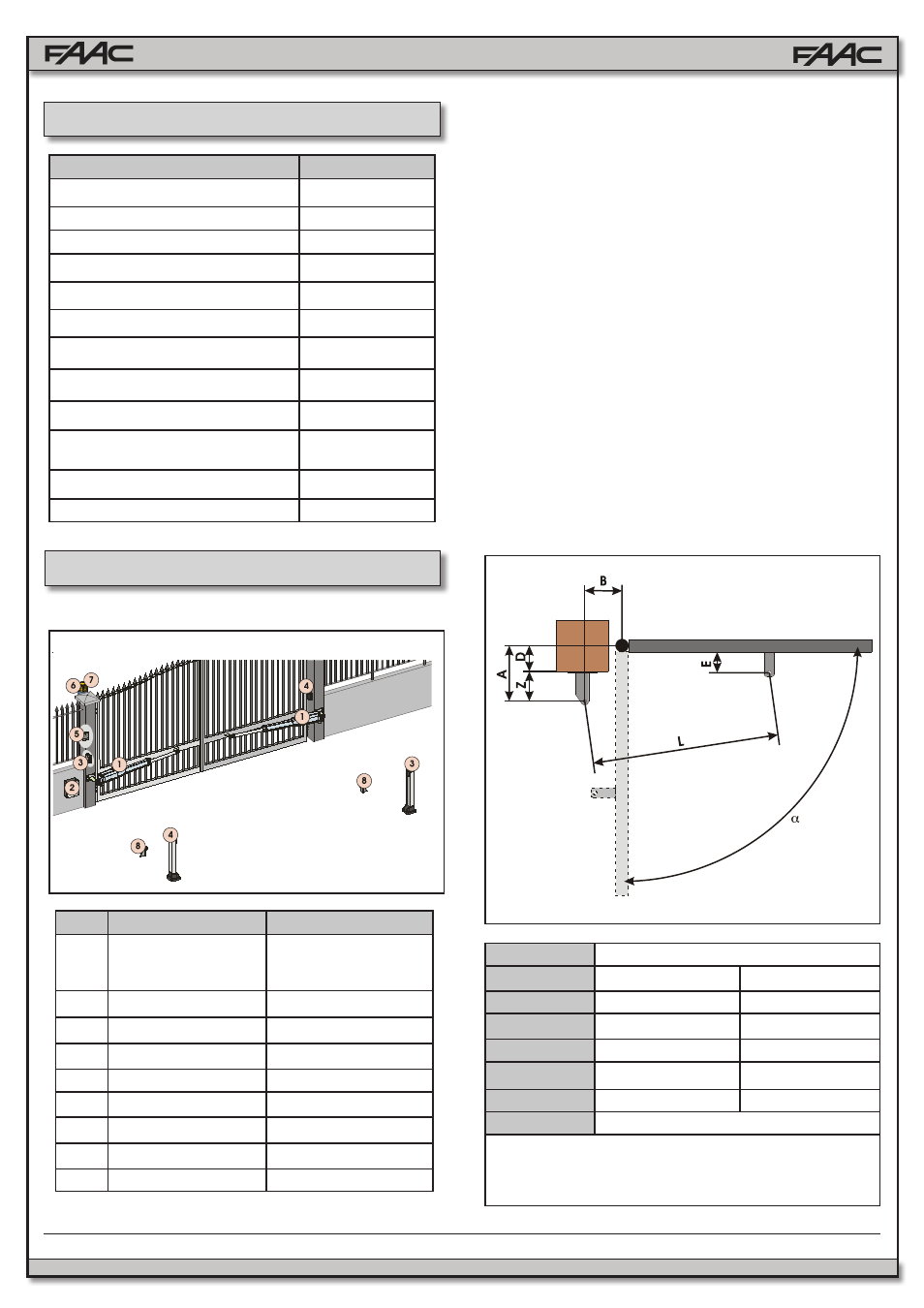
4.3 Installation Dimensions
Determine the mounting position of the operator with
reference to Fig. 4.
Ensure that the distance between the open leaf and any
obstacles (walls, fences etc.) is greater than the dimensions
of the operator.
* Dimensions
in Inches
7
FAAC Model 415 L LS 24V Swing Gate Operator
Fig. 3
Fig. 4
MODEL
415 L LS 24V
90°
110°
A
7⅝
6⅝
B
7⅝
6⅝
D
(1)
5
4⅜
Z
(2)
2¾
2¾
L
50¾
50¾
E
(2)
1¾
(1)
max. dimension
(2)
min. dimension