Set-up with a gate control unit (gcu), Additional gcu’s, Mount gcu – Controlled Products Systems Group WKP5LM3 User Manual
Page 2: Proceed to mount keypad
2
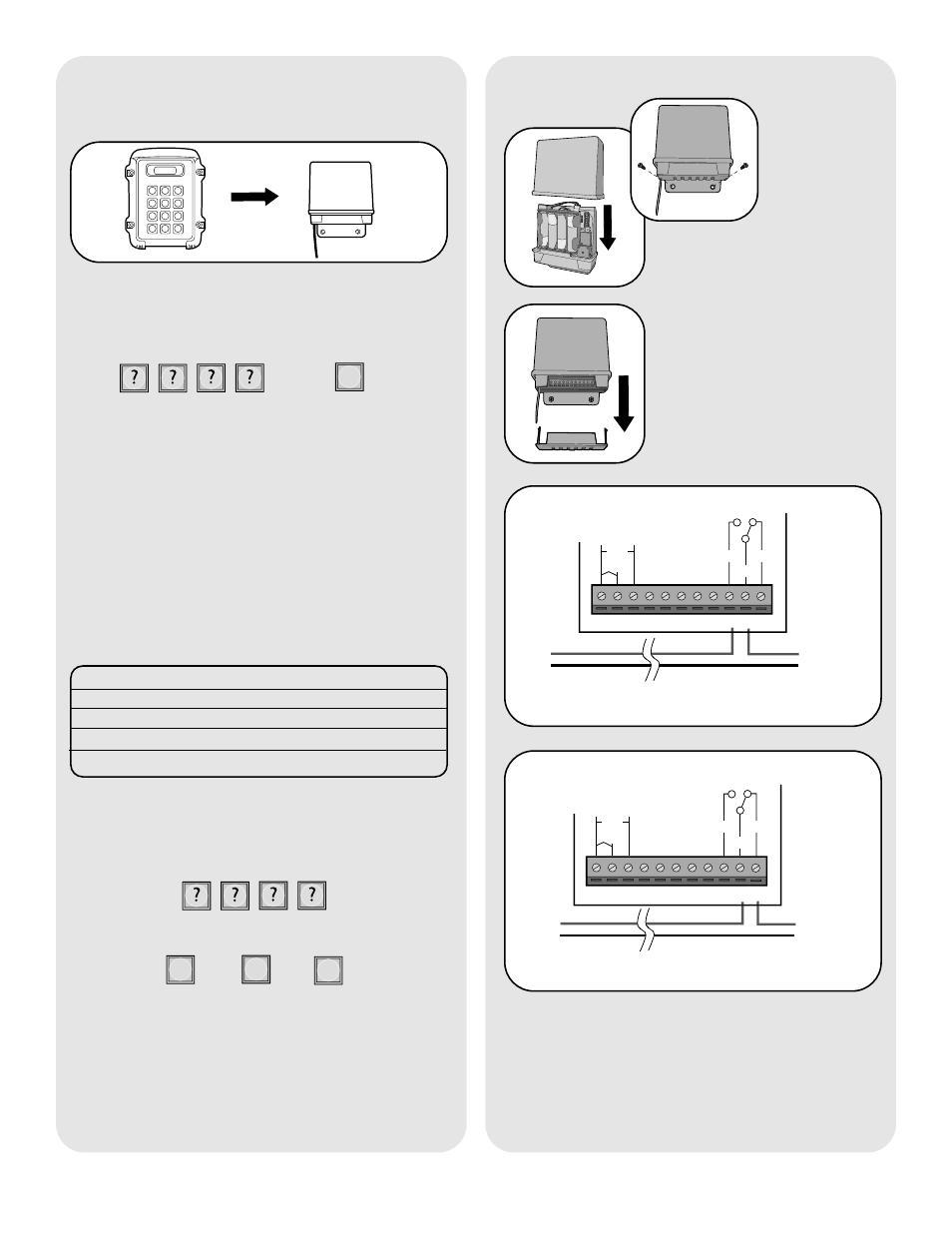
Additional GCU’s
NOTE: This step applies only if more than one GCU
is being used.
Up to four GCUs can be used. Each GCU will have to
have a different Identity. Set the Identity of the GCU
by changing the Dipswitches as shown in the chart
below. The Default Identity is 1.
GCU ID
Switch #1
Switch #2
1
OFF
OFF
2
ON
OFF
3
OFF
ON
4
ON
ON
Step 1: Press and hold the Learn button on the GCU
until the LED lights.
Step 2: Within 20 seconds, enter the Master PIN
Number on the main Keypad:
Followed by GCU Identity:
2
3
4
OR
OR
The Keypad will beep twice and GCU LED will blink
three times indicating programming is successful.
Repeat for additional GCU’s.
Mount GCU
Step 1: Replace GCU cover
and mount near gate operator
control box.
Step 2: Remove bottom panel
of GCU. Connect the Relay
Output of Receiver to the gate
or door. To connect to a Door
Strike or Magnetic Lock, see
diagrams below.
1
2
3
4
5
6
7
8
9
10 11
Proceed to Mount Keypad.
Set-Up with a Gate Control
Unit (GCU)
Step 1: Press and hold the Learn button on the GCU
until the LED lights.
Step 2: Within 20 seconds, enter the Master PIN
Number on the Main Keypad:
Then:
1
The Keypad will beep twice and GCU LED will blink
three times indicating programming is successful.
If an error tone is heard, the memory on the GCU will
need to be cleared by holding down the Learn button
until LED blinks a total of 8 times.
1 2
3
4
5
6
7
8
9
*
0
#
Cancel
1
3
2
4
5
6
7
8
9 10 11
DC
AC
+
-
COM
N/C
Door
Strike
Transformer/
Power Supply
Optional external power
input 10-24 Vac or DC
Door Strike- Normally Open (N/O) Connection
N/O
1
3
2
4
5
6
7
8
9 10 11
+
-
COM
N/C
Magnetic
Lock
Transformer/
Power Supply
Magnetic Lock- Normally Closed (N/C) Connection
DC
AC
Optional external power
input 10-24 Vac or DC
N/O