Mode switches, Lonworks network connection, Asynchronous channel connection – CTI Products NCB/AY with Serial Interface User Manual
Page 17: Lectrical, Onnections, The local l
CTI Products, Inc.
NCB-AY User Guide
2. Setup and Operation
11
NOTE: Set the “BAUDn” switch to 0 if the respective port will not be used. This is
important, as the front panel “ERR” LED will flash continuously if a serial port “BAUD”
switch is non-zero and no modem is connected.
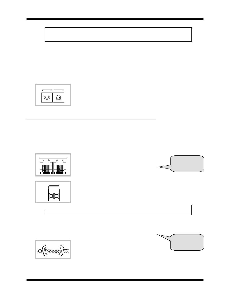
Mode Switches
“MODE 1” and “MODE 2” switches allow setting the NCB for compatibility with certain types of external
modems (i.e. dial-up or leased-line). A different type of modem can be connected to each port. NOTE:
previous versions of the NCB-IM unit have only one “MODE” switch. It this case, two modems can still be
connected to a single NCB unit, but they must both be of the same type (either both dial-up or both leased-line).
Set both “MODE” switches to 0 for proper operation of the NCB-AY.
S
TEP
3.
E
LECTRICAL
C
ONNECTIONS
LonWorks Network Connection
The local L
ON
W
ORKS
network must be attached to the NCB module via the “NETWORK” connector following
standard Echelon guidelines as to cable type, cable length, and termination appropriate for the selected
transceiver.
The dual RJ-45 “NETWORK” connector allows a
daisy-chained network connection method, as the
network pins of the two RJ-45 connector are directly
paralleled. Note that other pins on the RJ-45 are
connected to circuit ground and DC power.
The 2 pin removable terminal strip is wired in parallel with the network connections
on the dual RJ-45 connector.
NOTE: If your NCB module was purchased without a LonWorks
transceiver (SMX-ready), refer to Technical Note TN025 to install your SMX transceiver.
Asynchronous Channel Connection
Connect the asynchronous communication channel using the “PORT 1”
connector. The minimum set of signals that must be
connected are TXD, RXD, and ground. DTR/DSR
and RTS/CTS should be connected if available on the
channel. (See ‘OPTION B Switches’ information
above for signal details.) If DSR is not available, it must be strapped active by
connecting it to the DTR output of the NCB. If CTS is not available, sensing of it
must be disabled using the OPTION B Switches.
8 9
7
A
B
C
D
E
F
0
1
2
3
4
5
6
8 9
7
A
B
C
D
E
F
0
1
2
3
4
5
6
MODE 1
MODE 2
NETWORK
OUT
IN
NETWORK
PORT 1
1
2
3
4
6
7
8
9
5
See A
for pinouts and
cable diagrams.
See Appendix C
for Connector
Details