CTI Products IIB Console Interface User Manual
Page 21
IIB Hardware Reference
Special Installation Instructions
CTI Products, Inc.
68-10844-115
16
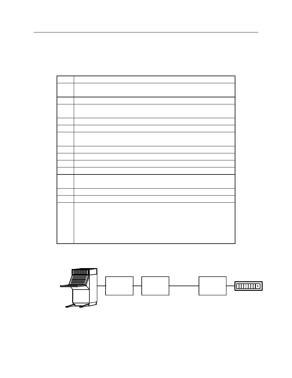
For example, Figure 10 shows a system with a single IIB and Comparator I/O
Module. The following steps show how the system might be setup, using the
following address assignments:
•
IIB address is Group 80, Module 0
•
Comparator I/O Module is Group 00, Module 0
Step
Action
1
Connect the network cable between the IIB NETWORK OUT port
and the Comparator I/O Module’s NETWORK IN port.
2
Power on both the Comparator I/O Module and the IIB.
3
On the Comparator I/O Module, set the Group switch to 00 and the
Module switch to 0.
4
Reset the Comparator I/O Module.
5
On the IIB, place OPTION switch 4 in the UP position.
6
On the IIB, set the Group switch to 00 and the Module switch to 0.
This is the address of the Comparator I/O Module it will work with.
7
On the IIB, set the receiver bank selector switches.
7
Press the RESET button on the IIB.
8
The IIB’s ERR LED will turn on and remain on.
9
On the IIB, place OPTION switch 4 in the DOWN position.
10
On the IIB, set the Group switch to 80 and the Module switch to 0.
This is the IIB’s own address.
11
Press the RESET button on the IIB.
12
The ERR LED will turn on momentarily and then turn off.
13
After a couple of seconds, the ACT LED on the IIB should turn ON
and the ACT LED of the Comparator I/O Module should turn ON
or begin blinking.
If this does not occur, repeat the process or consult the
troubleshooting guide in section 10.
CA-80034-100
CA-80034-100
MODULE
IIB
COMPARATOR
I/O
CONSOLE
ELECTRONICS
COMPARATOR
MCN NETWORK
CONSOLE
Figure 10 - Unit Address Programming Example