Codelocks Upgrade - Audit Trail Kit for CL5010 User Manual
Page 3
3
REVERTING TO FACTORY SETTING
If the Master Code is not known the lock memory can be cleared and
made to revert to the factory Master Code as follows:
•
Remove battery
•
Press and hold ‘0’ button
•
Refit battery
•
Within 7 seconds press ‘000’
•
Lock will be reset to factory default settings (AT option only).
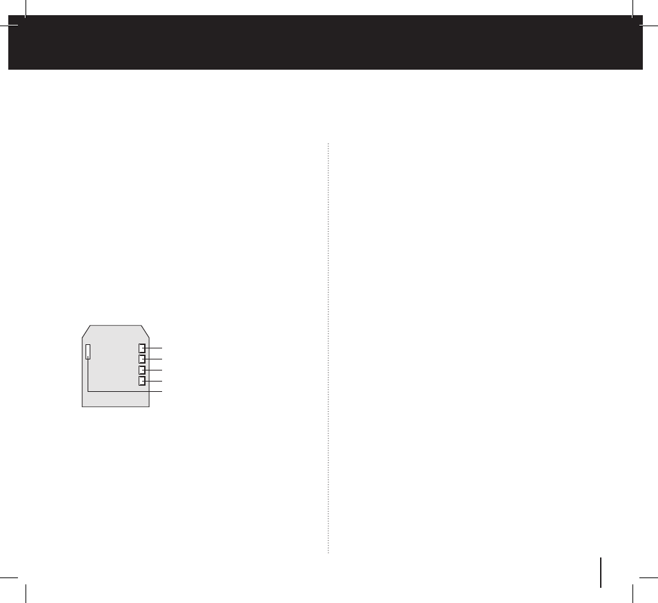
1. Battery
2. Remote 1
3. Remote 2
4. Clutch / Actuator
5. Data Cable Connector
REM 2
is intended for use when there is a need for the door to be
released by an alarm system, such as a fire alarm. This enables
emergency personnel to rapidly check that no one is trapped,
overlooked in classrooms, wards, guest rooms, etc. during an
emergency evacuation, or during a fire drill. When activated by
an alarm REM 2 will maintain the unlocked condition for 30
minutes. During this time the Red LED will flash once every
second and BEEP to indicate the unlocked condition. The lock
will automatically revert to normal after 30 minutes. If required
Program 11 can be used to revert the lock to normal before the
30 minute period has finished.
LOCKED/UNLOCKED STATUS INDICATION
Using Program 15 the Blue and Red LEDs can be programmed
to indicate locked and unlocked status.
BATTERY POWER
The CL5000 Electronic should provide in excess of 200,000
openings from the 4 x AA cells rated at 2,900 mAh.
LOW BATTERY
When the battery power is low the Red LED will flash 5 times
before the Blue LED flashes to signal acceptance of the code.
Batteries should be changed as soon as this happens.
REM 1
is intended for use when there is a need to allow a
visitor to open the door after having been identified by intercom
or by sight from within. REM 1 would be connected to a push
button on a reception desk, or to the appropriate button on an
intercom. Pushing the button would cause the Blue LED to light
and would release the lock for the normal set time.
REMOTE RELEASE OPTION
The lock has 2 sets of terminals for remote release, labelled
REM 1 and REM 2 on the printed circuit board in the front housing.
Cables are provided with the lock for these connections.