CNB HDS4848DV User Manual
Page 12
12
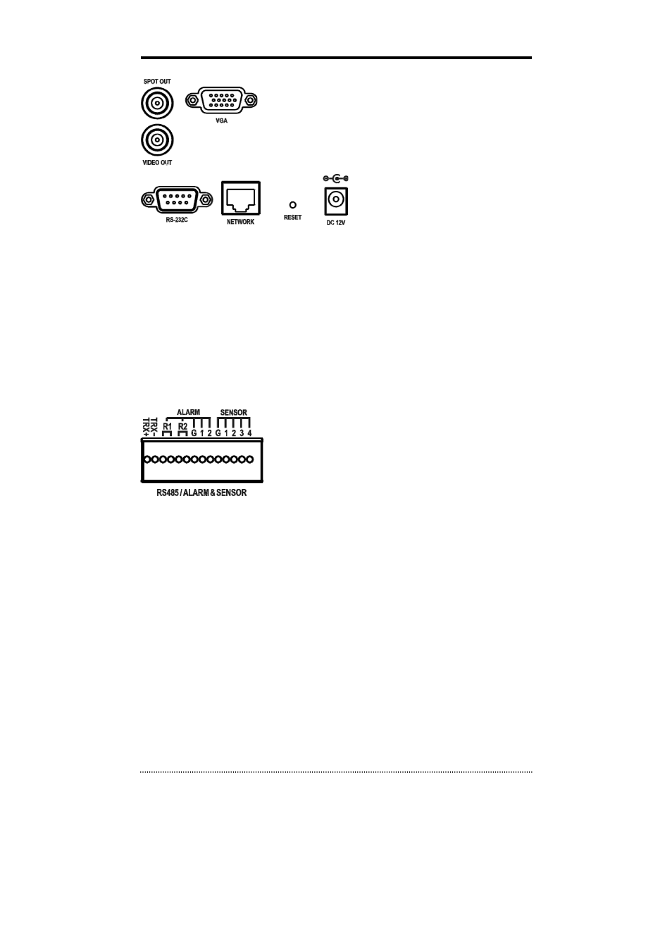
Video Output
Connect the main monitor to either the Video Out (CVBS) or VGA out
connector. Connect the spot monitors to the SPOT OUT connectors as
needed.
ETC
• RS-232C: An RS-232C connector is provided to connect an ATM or POS machine for Text-In
function. Use a cable with a DB9 (female) connector to connect to the DVR.
• Network: Connect a Cat5 cable with an RJ-45 connector to the DVR connector for remote
monitoring, remote playback, and remote setup. See
Chapter 3-2. DVR Configuration
for
configuring the Network connections.
• Reset: The DVR has a Reset switch that will only be used to return all the settings to the original
factory settings. To reset the unit, turn the DVR off first. Turn it on again while poking the
straightened paperclip in the reset hole. Hold the switch until the DVR is initializing.
• Power Connector: Connect adapter cable to the power connector on the rear panel. (DC12V,
3.33A) Input AC power to the adapter. (free voltage from 100V to 240V, 50/60Hz)
RS485/ALARM/SENSOR
The RS485 connector can be used to control PTZ cameras. The DVR
can also be controlled remotely by a control keyboard.
4 alarm output connectors are provided to connect external alarms
such as sirens or lights. 2 alarm output connectors have internal
relays and the others are TTL signals.
4 sensor input connectors are provided to connect external devices. You can use sensors to signal the
DVR with event. To make connections on the terminal block, press and hold the button and insert the
wire in the hole below the button.