American Power Conversion 100 VAC User Manual
Page 10
990-7096 Rev. 2
6
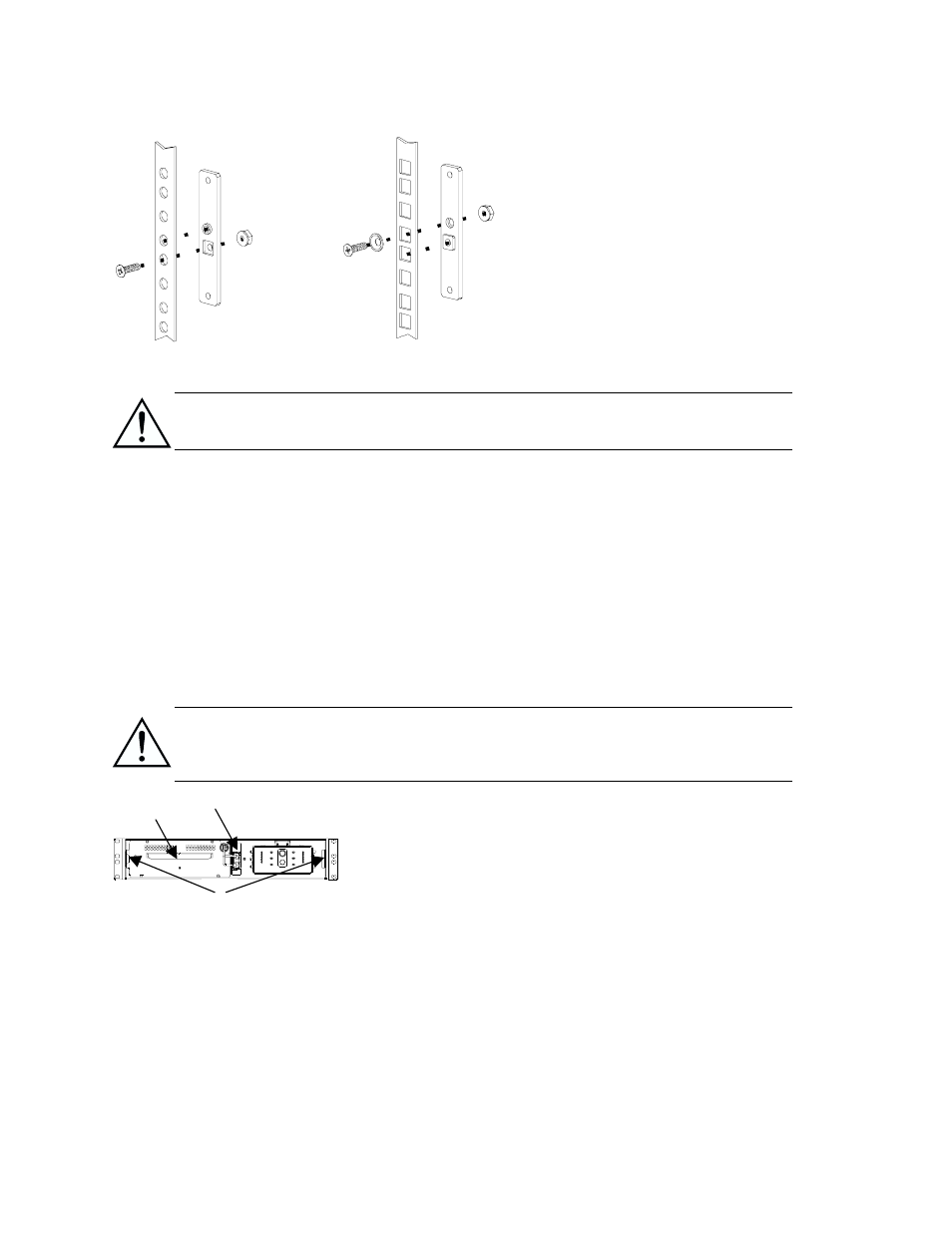
Two-Post Racks
1. If the rack holes are not 10-32
threaded, first attach the backing plate
supplied (870-1148)
to the rack.
2. Support the UPS from the front and
back. Insert the four (4) ornamental
screws supplied with the UPS
through the mounting brackets and
into the top and bottom holes in the
U-space as shown for the Four-Post
Rack. Screw them into the threaded
holes of the backing plate.
Removing the UPS from the Rack
Due to the weight of the UPS, two people are required to remove it from the rack.
1. Remove the front panel bezel: Face the front of the UPS, and, using both hands, insert each
index finger behind the lip of the curved section of the front panel bezel and pull towards you.
2. Unscrew the four ornamental screws (two screws on each mounting bracket).
3. Position one person in front of the rack and the second person either behind or on one side of
the UPS for additional support.
4. Using the battery tray handle to support the front of the unit, slide the UPS partially out of the
rack.
5. Supporting the UPS from the bottom or rear of the unit, slide the UPS fully out of the rack.
Connect the Battery and Attach the Front Panel Bezel
The UPS is shipped without its battery connected and the front panel bezel installed (it
is packaged separately within the main box). You must connect the battery and install
the plastic front panel bezel before the installation is complete.
1. Facing the front of the UPS, locate the battery cable (in the
center of the unit) and remove the tape to expose the cable
connector.
2. Locate the UPS battery connector
which is to the right of the
battery tray
and recessed. Connect the battery cable
connector to the UPS connector. Press firmly to ensure that the
connection is tight. You will hear a “snap” when the connector
is properly seated. Also, as a visual indication, the back of the
connector should be recessed (~0.64 cm) from the sheet metal