CNB IBP5030CR User Manual
Page 8
Network Weatherproof Camera Installation Manual
8 / 20
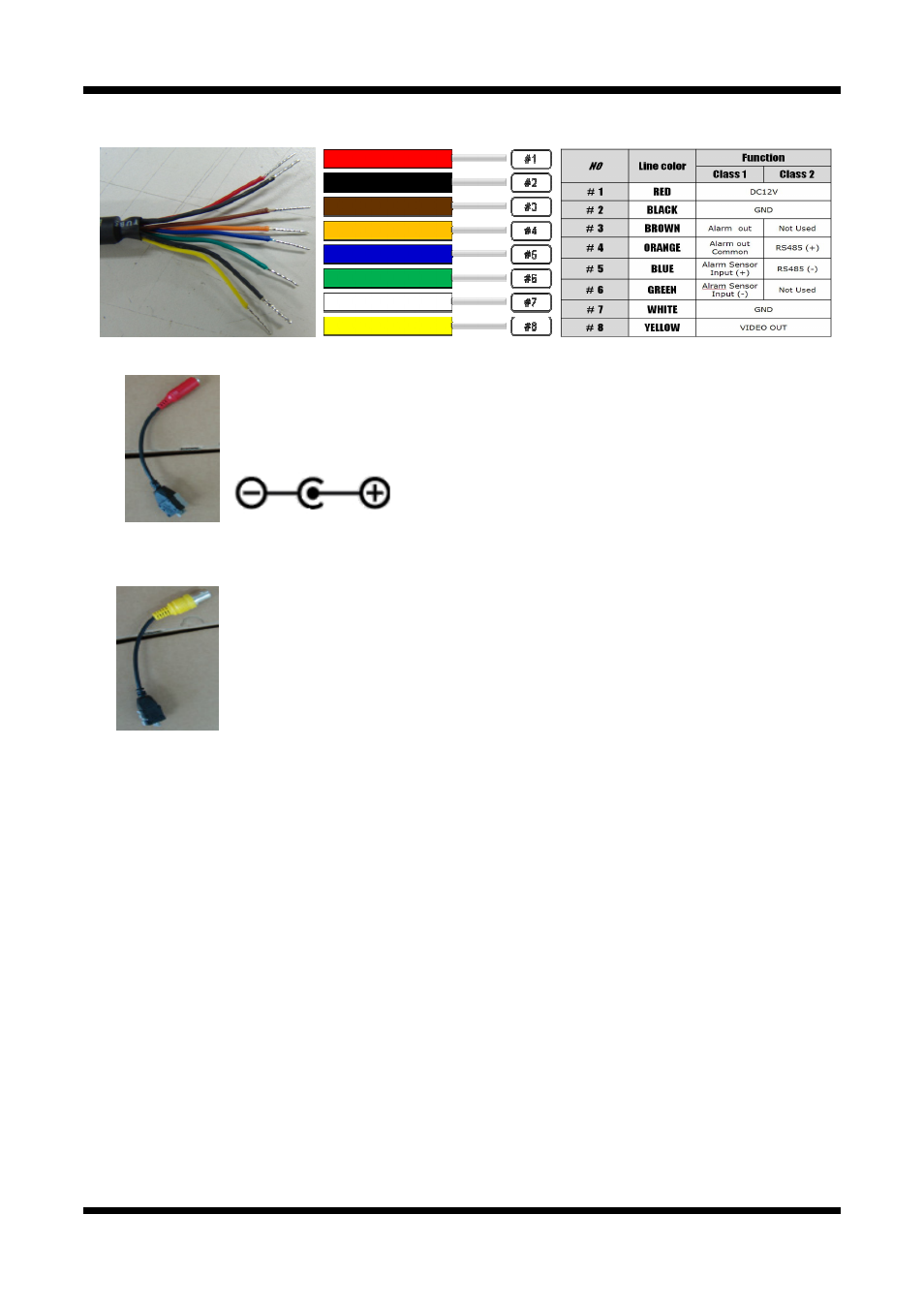
2.3.3 Cable Connection
z
Power Input(#1, #2)
Use the cable adapter in the package to connect power.
Red –+12V DC, Black - GND
Please use the accessory power supply provided in the package. (DC12V/5A)
z
Analog Video Output (#7, #8)
Use this output for immediate monitoring of the video during installation.
Use the supplied cable adapter (Yellow for video and White for Video GrounGGND)
This adapter can be connected to a cable through a BNC termination.
(Select Video Out at menu screen to enable this output)
z
Alarm Connection (Class 1 ONLY)
These wires connect to Alarm input/output devices.
Alarm Sensor Input: Connect to Alarm sensor devices such as IR Sensor or Heat sensor. These can
be configured to
normally close or normally open operation. (#5, #6)
Alarm Output: Connect to Alarm devices such as Relay operated
Siren Lamp or Alarm Light.
These can be configured to
normally close or normally open operation. (#3, #4)
Please refer to “2.3.6 Connection to Alarm Devices” for detailed instruction on how to connect
sensors and Relays.
z
RS-485
Open up the rear cap. Connect the cable from Class 1 to Class 2.
This is to control P/T(Pan/Tilt) device by RS485 interface