4 mounting the transducer, Ounting the, Ransducer – Cleveland Motion Controls ULTRA ISC CANTILEVER TRANSDUCER CLTSCM REV AA User Manual
Page 29
MAN-70445-0
R
EV
AA
U
LTRA
S
ERIES
ISC
C
ANTILEVER
T
RANSDUCER
T
ECHNICAL
M
ANUAL
4.4 M
OUNTING THE
T
RANSDUCER
The mounting surface for the transducer should be flat and true to the web path. Remove any loose paint,
rust or scale from the machine frame before mounting. A clean metallic surface helps ensure that the body
of the transducer is at frame potential.
Table H – Steps for Mounting an Ultra Series Transducer
If you are using this
type of Mounting
style:
Then, perform these steps:
Stud (S)
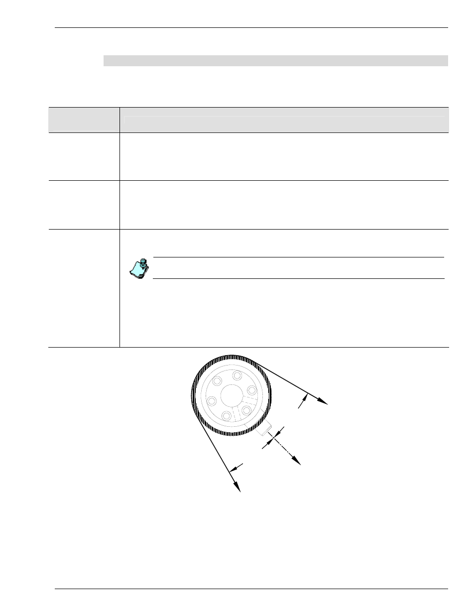
Before tightening the mounting bolt, rotate the transducer body until the force direction (indicated by the arrow on the
label) is aligned with the vector of the web force. The vector of the web force is the bisector of the wrap angle. Refer
to
Pillow Block and
Bearing
Replacement (PB,
BR)
1. Loosely mount the transducer by lightly tightening the four (4) socket head cap screws that hold the lock plate to
the back of the transducer.
2. Rotate the body of the transducer body until the direction of the force (indicated by the arrow on the label) is
aligned with the vector of the web force.
3. Tighten the four (4) socket head cap screws to securely clamp the transducer in position.
Flange (F)
1. Before drilling the four (4) mounting holes, determine the orientation of the transducer taking into consideration
the location of the mounting screws. Be sure that the screws do not interfere with the position of the connector.
An optimal location for mounting holes also lets you maximize rotational alignment range.
Do not use the flange assembly as a drill template while not mounted to the transducer. The spacing
between flange halves is different when the transducer body is added.
2. Adjust the alignment of the transducer. First, be sure that the four (4) flange bolts are loose and then, loosen the
two (2) bolts that draw the flange halves together.
3. Rotate the body of the transducer body until the direction of the force, indicated by the arrow on the label, is
aligned with the vector of the web force.
4. Secure the flange to the transducer. Tighten the two (2) socket head cap screws that draw the flange halves
together.
5. Tighten the four (4) bolts that draw the flange to the mounting surface.
LOAD
DIRECTION
WRAP
ANGLE
BISCETOR
WE
B
WRAP
ANGLE
BISECTOR
W
EB
Figure 12 - Proper Orientation of the Cantilever Transducer
Although this figure shows an Ultra Cantilever transducer, it is also applicable to the Ultra ISC Cantilever transducer.
21