INSTEON In-LineLinc Relay (2475S2) Manual User Manual
Page 5
Page 5 of 14 Rev: 1/21/2014 7:57 AM
6)
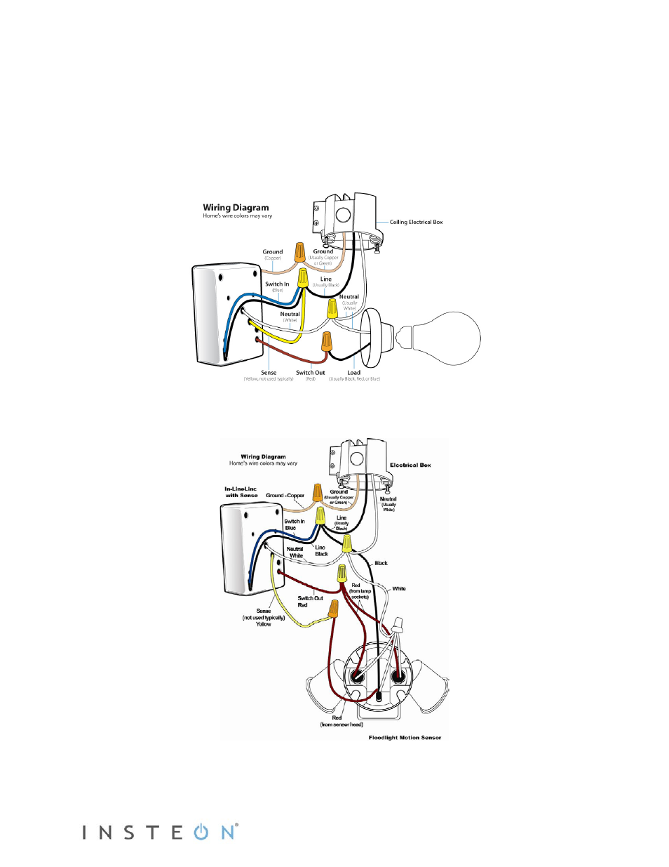
Referring to the diagrams below, use the included wire nuts to connect the fixture’s Line, Load,
Neutral, Ground and Sense wires (if using) to In-LineLinc’s corresponding wires.
7)
Enable power to the switch from the circuit breaker or fuse panel.
8)
Use In-LineLinc’s On and Off buttons to test that In-LineLinc is installed properly.
The load will turn on and off.
9)
Link In-LineLinc to an INSTEON controller.
10)
Gently place In-LineLinc into the junction box, making sure nothing could accidentally press the
buttons on its face.
11)
Reinstall the fixture.
Above: wiring In-LineLinc Relay without Sense; below, wiring In-LineLinc with Sense.
See also other documents in the category INSTEON Hardware:
- SwitchLinc Dimmer (2476D) Quick Start (1 page)
- SwitchLinc Dimmer (2476D) Manual (21 pages)
- SwitchLinc Relay (2476S) Quick Start (1 page)
- SwitchLinc Dimmer (Dual-Band) - (2477D) Manual (Prior to Version 7.0) (16 pages)
- SwitchLinc Dimmer, High Wattage (Dual-Band) (2477DH) Quick Start (12 pages)
- SwitchLinc Dimmer (Dual-Band) - (2477D) Manual (Version 7.0 and Newer) (16 pages)
- SwitchLinc Relay (Dual-Band) (2477S) Quick Start (12 pages)
- SwitchLinc Relay (Dual-Band) (2477S) Manual (18 pages)
- SwitchLinc Dimmer, High Wattage (Dual-Band) (2477DH) Manual (15 pages)
- SwitchLinc 2-Wire Dimmer (RF) (2474DWH) Manual (15 pages)
- SwitchLinc 2-Wire Dimmer (RF) (2474DWH) Quick Start (1 page)
- SwitchLinc Dimmer 100-277VAC (dual band) (2478D) Manual (19 pages)
- SwitchLinc Dimmer 100-277VAC (dual band) (2478D) Quick Start (2 pages)
- ToggleLinc Dimmer (2466DW) Manual (20 pages)
- ToggleLinc Dimmer (2466DW) Quick Start (1 page)
- ToggleLinc Relay (2466SW) Manual (18 pages)
- ToggleLinc Relay (2466SW) Quick Start (1 page)
- KeypadLinc Dimmer, 6 button (2486DWH6) Manual (24 pages)
- KeypadLinc Dimmer, 6 button (2486DWH6) Quick Start (2 pages)
- KeypadLinc Dimmer, 8 button (2486DWH8) Quick Start (2 pages)
- Keypad Dimmer (Dual-Band) (2334-2xx US) Manual (24 pages)
- Keypad Dimmer (Dual-Band) (2334-2xx US) Quick Start (2 pages)
- KeypadLinc Relay (2487S) Quick Start (2 pages)
- KeypadLinc Relay (2487S) Manual (25 pages)
- KeypadLinc Timer (2484DWH8) Manual (26 pages)
- KeypadLinc Timer (2484DWH8) Quick Start (2 pages)
- LampLinc Dimmer Module (Dual-Band) (2457D2) Manual (33 pages)
- LampLinc Dimmer Module (Dual-Band) (2457D2) Quick Start (8 pages)
- On/Off Module (Dual-Band) (2635-222) Manual (28 pages)
- On/Off Module (Dual-Band) (2635-222) Quick Start (8 pages)
- ApplianceLinc (2456S3) Manual (12 pages)
- ApplianceLinc Outdoor (2456S3E) Manual (14 pages)
- ApplianceLinc Outdoor (2456S3E) Quick Start (1 page)
- Outdoor On/Off Module (Dual-Band) (2634-222) Manual (13 pages)
- Dimmer Module - 2632-422 (France), 2632-432 (Germany), 2632-442 (UK), 2632-522 (AUS/NZ) Quick Start (1 page)
- Dimmer Module - 2632-422 (France), 2632-432 (Germany), 2632-442 (UK), 2632-522 (AUS/NZ) Manual (16 pages)
- On/Off Module - 2633-422 (France), 2633-432 (Germany), 2633-442 (UK), 2633-522 (AUS/NZ) Quick Start (1 page)
- On/Off Module - 2633-422 (France), 2633-432 (Germany), 2633-442 (UK), 2633-522 (AUS/NZ) Manual (14 pages)
- OutletLinc Dimmer (Dual-Band) (2472DWH) Quick Start (1 page)
- OutletLinc Dimmer (Dual-Band) (2472DWH) Manual (13 pages)
- OutletLinc Relay (2473SWH) Quick Start (1 page)
- OutletLinc Relay (2473SWH) Manual (14 pages)
- DIN Rail Dimmer - 2452-222 (US), 2452-422 (EU), 2452-522 (AUS/NZ) Quick Start (2 pages)
- DIN Rail Dimmer - 2452-222 (US), 2452-422 (EU), 2452-522 (AUS/NZ) Manual (19 pages)
- DIN Rail On/Off - 2453-222 (US), 2453-422 (EU), 2453-522 (AUS/NZ) Quick Start (2 pages)