Electrical installation – Hach-Lange EVITA OXY User Manual User Manual
Page 16
14
The transmitter is connected using the two-wire,
shielded cable. The two leads carry supply voltage,
a 4-20 mA current signal, and HART
®
communication.
Examples of coupling to loop-powered display and
PLC/SCADA system are shown in fi g. 22, fi g. 23 and
fi g. 24, respectively.
+
–
Shield
Black
Red
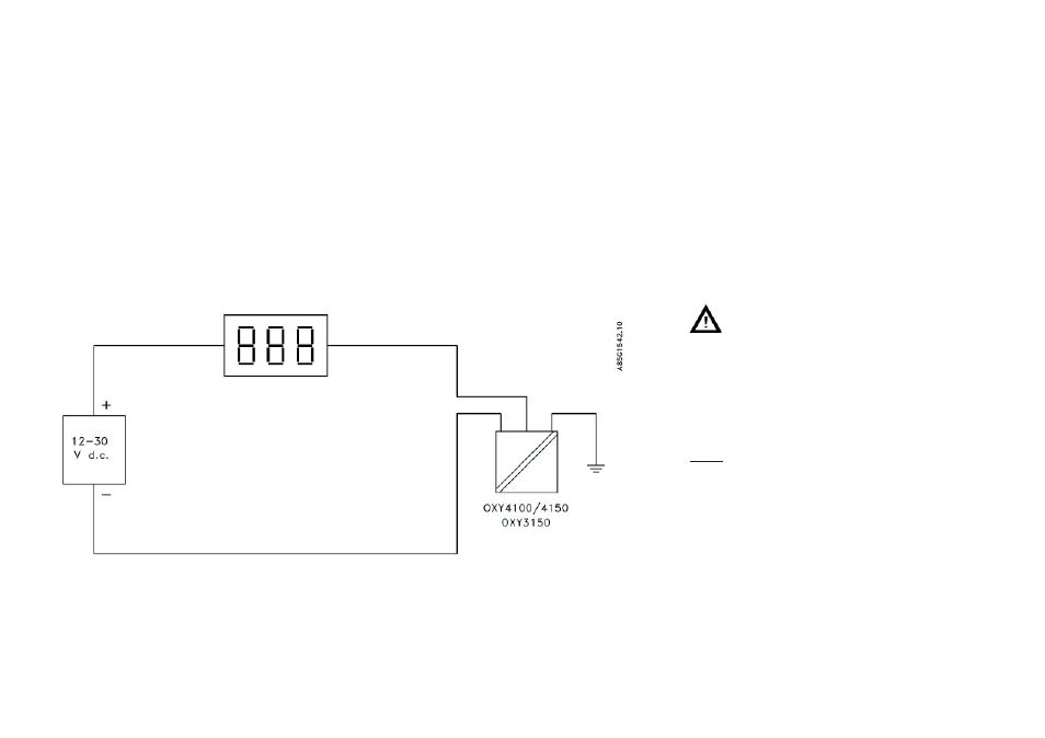
Fig. 22
EVITA
®
OXY connected to loop-powered display.
Electrical installation
OXY 4100/4150/3150 stand alone transmitter
If the cable is extended, the total length of the cable
must not exceed 1000 m (3000’). Always use two-
wire, shielded cable for the extension (min. 2 x 0.2
mm
2
(24 AWG)).
A suitable power supply shall be considered
in the end-use application. The power supply
must be a Class 2 power source (limited
circuit) according to the National Electrical
Code (NEC) and provided double/reinforced
insulation between mains and the 12-30 V
d.c. supply for the oxygen transmitter.
Note:
Components like motors, pumps and
computers may cause high voltage potential
differences between the protective earth/
ground wire and the water in the tank, that
results in unstable readings. If this problem
occurs, mount an earthing electrode in the
tank to equalise the electrical potential of the
water to PE.
If the fl ow velocity in the tank is high, it may
cause a static potential locally. Is this the
case, mount the earthing electrode close to
the transmitter.