Clear-Com FIM-202D User Manual
Page 8
Clear-Com Communication Systems
FIM-202D Matrix Fiber Interface Instruction Manual
1 - 2
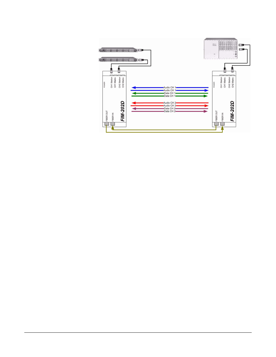
Figure 1-2: Connecting Intercom Panels to the Central Matrix
1. Matrix Plus 3 and Eclipse intercom panels transmit analog audio
signals and digital data signals to the first FIM-202D unit via
standard Ethernet copper cable terminated with RJ-45 connectors.
2. The first FIM-202D unit converts the analog audio signals to digital
audio signals through an analog-to-digital converter (ADC) located
on the FIM-202D unit’s main circuit board.
3. The first FIM-202D unit then multiplexes (combines) the digital audio
signals with the already digital data signals.
4. The first FIM-202D then converts the multiplexed digital signal into
an optical signal.
5. The first FIM-202D then transmits the optical signal over
fiber-optical cable to the second FIM-202D unit, where a similar but
reverse process occurs to convert the signal back to its original
format.
6. The second FIM-202D unit converts the received optical signal to a
digital signal.
7. The second FIM-202D then “demultiplexes” (separates) the digital
signal back into it’s separate audio and data signals for each
intercom unit.
8. The second FIM-202D then converts the digital audio signals for
each intercom panel to analog audio signals by sending the signals
through a digital-to-analog converter (DAC) located on the
FIM-202D unit’s main circuit board.
9. The second FIM-202D unit then transmits the analog audio and
digital data signals for each intercom panel to the central matrix over
standard Ethernet copper cable terminated with RJ-45 connectors.