4 - za4 wiring diagram – CAME Ati-P324 Kit User Manual
Page 30
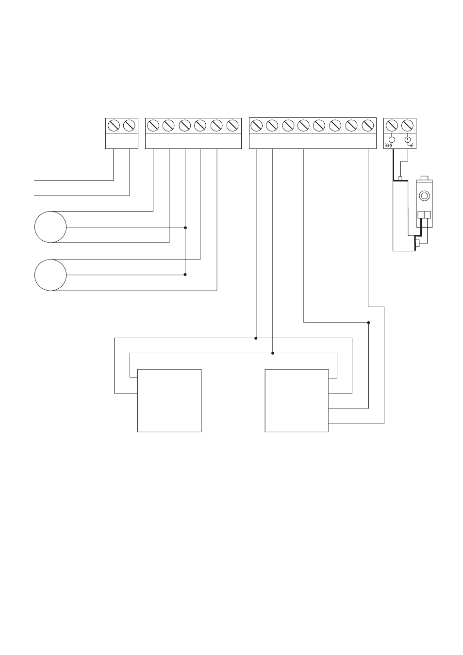
5.4 - ZA4 Wiring Diagram
Terminals 1 and 2, 2 and C1 are normally closed circuits and if
they are not used they must be linked
L1 L2 U V W X Y E1 10 11 1 2 3 5 7 C1
Co-axial cable
230V A/C
M1
Single-Phase motor
Single-Phase motor with leaf delay
on closing cycle
M2
11 TX
10
Safety beams which are connected to obtain Re-opening
During the closing cycle
RX
11
10
C
NC
29
This manual is related to the following products:
See also other documents in the category CAME Safety:
- Frog-AE (10 pages)
- Frog-A 230v (10 pages)
- Frog-A 24v (12 pages)
- Myto ME (20 pages)
- Myto-C (8 pages)
- Ferni 230v (12 pages)
- Ferni 24v (12 pages)
- F1003 Stop Arm (2 pages)
- Amico (14 pages)
- Frog-PM (18 pages)
- Frog-PC (8 pages)
- Frog-J (16 pages)
- Stylo (20 pages)
- Krono (10 pages)
- Fast (24 pages)
- Axo (18 pages)
- Axo-P324 Kit (32 pages)
- Superfrog (12 pages)
- Bx-243 (22 pages)
- BX74 - BX78 (24 pages)
- BX-P (Pratico) (18 pages)
- BX10 (34 pages)
- BX-241 (16 pages)
- BX-246 (24 pages)
- Bk (22 pages)
- Ver (24 pages)
- FrogAE-P Kit (32 pages)
- FrogAE-S Kit (32 pages)
- Ati-S Kit (36 pages)
- FerniE-P24 Kit (36 pages)
- FerniE-S24 Kit (36 pages)
- Krono-P3 Kit (32 pages)
- Axo-P3 Kit (30 pages)
- BK-12P Kit (18 pages)
- Ver U4483-B Kit (22 pages)
- Gard6S Kit (24 pages)
- Gard4S Kit (24 pages)
- Gard2S Kit (12 pages)
- G4230ST Kit (16 pages)
- G424VST Kit (16 pages)
- G6230ST Kit (16 pages)
- G624VST Kit (16 pages)
- Flex U8600 Kit (8 pages)
- Tra08 (12 pages)