3 description board bn1, English, 5 gearmotor end-stop connection – CAME BX-241 User Manual
Page 9: 4 emergency battery connection
".
!
"
#
$
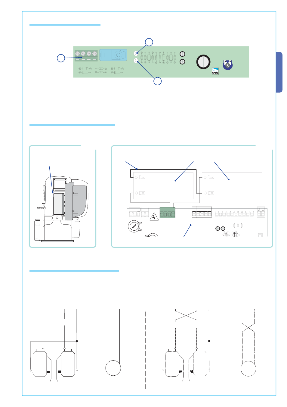
6.3 Description board BN1
1 - ZBX241 board connecting terminal board
2 - The green LED indicator light signals mains power supply on
3 - The red LED indicator light signals emergency battery power supply on
3
1
2
9
A
ll t
h
e d
at
a a
n
d i
n
fo
rm
at
io
n c
o
n
ta
in
ed h
er
ei
n
i
s c
o
n
si
d
er
ed
s
u
b
je
ct to c
h
an
g
e a
t a
n
y t
im
e a
n
d a
t o
u
r d
is
cr
et
io
n
ENGLISH
•••
•
,).%
FC F
M
FA
N
•
•
•
•
•
•
••
•
•
•
•
•
+ T.P.A. -
••
•
•
•
•
•
•
•
•
•
•
•
•
•
•
•
•
••
•
••
•
••
•
•
••••
••
•
•
•
•
•
•
•
•
•
•
•
•
•
•
•
•
•
•
•
•
•
•
•
•
•
•
•
•
•
••
•
•
•
•
•
•
•
•
•
•
•
• • • • •• • •
• • • • •• • •
10 11 E1
1
2
3
3P C1 C3 7
24V AC +
-
L1T L2T
L1
L2
BATTERY
D
C
B
A
+ T.A.C. -
+ SENS. -
PROGRAM.
CH1
?
?
6.5 Gearmotor end-stop connection
FA
FC
F
M
N
NC
NC
M
FA
FC
F
M
N
NC
NC
M
6.4 Emergency battery connection
Limit switch unit
24V (d.c.) single-phase motor
Limit switch unit
The motor and limit switch unit are wired at the factory for mounting on the left-hand side of the gate (as seen from the inside).
If right-hand installation is desired:
- invert limit switch connections FA-FC on the terminal block;
- invert motor phase connections M-N on the terminal block.
24V (d.c.) single-phase motor
Insert batteries in the appropriate bracket (Fig.1) and connect them (using the cables provided) to the ZBX241 board (Fig.2)
terminal (+,-).
12V - 1.2 Ah emergency batteries
NOT INCLUDED
Bridge connection
lead
FIG.1
Battery bracket
FIG.2
The BN1 board allows the automation to be battery operated in case of a power outage. When power is restored, the card also
recharges the batteries.
ZBX241 board