English, 3 cable list and minimum thickness, 4 standard installation – CAME FrogJ-S Kit User Manual
Page 5
5
ENGLISH
T
h
e d
at
a a
n
d i
n
fo
rm
at
io
n s
h
ow
n i
n
t
h
is
d
ia
lo
g
u
e m
ay b
e c
h
an
g
ed by C
am
e C
an
ce
ll
i A
u
to
m
at
ic
i S
.p
.A
. a
t a
n
y t
im
e w
it
h
o
u
t p
ri
o
r w
ar
ning
.
N.B.: If the cable length differs from that specified in the table, then you must determine the proper cable diameter in the basis
of the actual power draw by the connected devices and depending on the standards specified in CEI EN 60204-1.
For connections that require several, sequential loads, the sizes given on the table must be re-evaluated based on actual power
draw and distances.When connecting products that are not specified in this manual, please follow the documentation provided
with said products.
5.3 Cable list and minimum thickness
Connections
Type of cable
Length of cable 1 < 10 m
L. of cable 10 < 20 m L. of cable 20 < 30 m
Control panel power supply 230 3F
FROR CEI
20-22
CEI EN
50267-2-1
3G x 1,5 mm
2
3G x 2,5 mm
2
3G x 4 mm
2
Motor power supply 24V
3 x 1 mm
2
3 x 1,5 mm
2
3 x 2,5 mm
2
flashing lamp
2 x 0,5 mm
2
2 x 1 mm
2
2 x 1,5 mm
2
Photocell transmitters
2 x 0,5 mm
2
2 x 0.5 mm
2
2 x 0,5 mm
2
Photocell receivers
4 x 0,5 mm
2
4 x 0,5 mm
2
4 x 0,5 mm
2
Accessories power supply
2 x 0,5 mm
2
2 x 0,5 mm
2
2 x 1 mm
2
Control and safety devices
2 x 0,5 mm
2
2 x 0,5 mm
2
2 x 0,5 mm
2
Antenna connection
RG58
max. 10 m
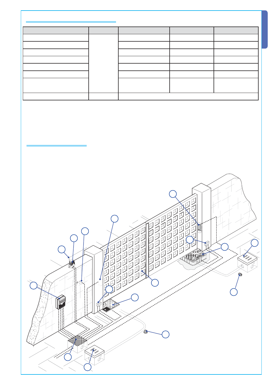
1) FROG-J unit
2) Control panel
3) Custom key release
4) Shunt box for connecting the gearmotor
5) Reception antenna
6) Flashing light
7) Selector switch
8) Photocells
9) Electric cable junction box
10) Drainage pit
11) Mechanical gate stops
5
2
8
8
7
9
10
6
1
4
4
11
11
3
10
11
5.4 Standard installation