Gardner Bender GDT-3190 4 Function Multimeter User Manual
4 function, 14 rang e digital multi-meter, Multímetr o digital de 4 funciones, 14 rangos, Gdt -3190
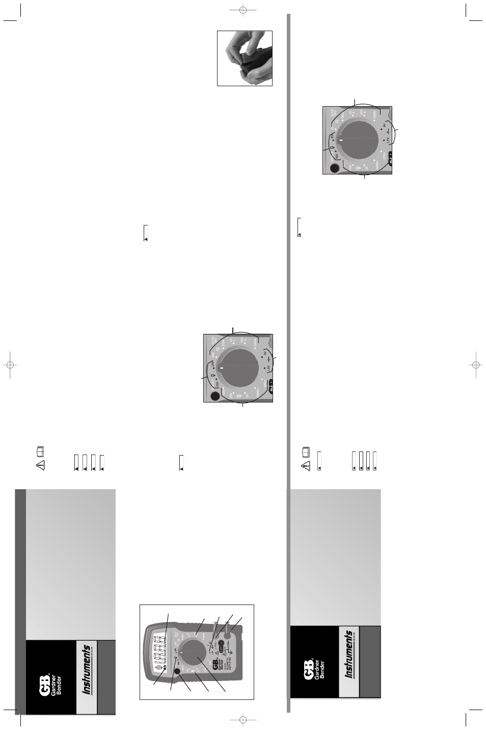
Dial Settings
3.1 A
C
V
olts
There are tw
o r
anges f
o
r measur
ing A
C
v
oltage
, 200
V and 500
V
.
F
o
r more accur
ate measurements under 200 v
olts use the
200 V
olt
setting.
1.
Set the function/r
ange s
witch to the appropr
iate A
C
V r
ange sho
wn abo
v
e
.
2.
T
ouch the test leads to the circuit under test.
With A
C
v
oltage
, the polar
ity of the test leads is not a f
a
ctor
.
NO
TE:
It is best to touc
h one of the test leads to gr
ound or Neutral fir
st and then touc
h the 2nd test lead to the hot wire
.
3.
Read the v
alue of the measurement displa
y
ed.
4.
T
ypical A
C
V
oltage measurements include w
all outlets
, appliance outlets
, motors
, light fixtures and s
witches
.
W
hen measur
ing o
utlets the
specially spaced lead holders allo
w f
or single one hand testing.
3.2 DC
V
olts
There are f
our r
anges f
o
r measur
ing DC v
oltage
, 2, 20, 200
V and 600
V
.
F
o
r more accur
ate measurements use the lo
w
est r
ange poss
ib
le
without e
xceeding the v
alue
.
1.
Set the function/r
ange s
witch to the appropr
iate DC
V r
ange sho
wn abo
v
e
.
2.
T
ouch the test leads to the circuit under test.
With DC v
oltage
, the polar
ity of the test leads is a f
actor
.
T
ouch the b
lac
k (c
ommon) test lead
to the negativ
e DC source first and red (positiv
e) test lead to the
“liv
e”
source second.
3.
Read the v
alue of the measurement displa
y
ed.
If the leads are re
v
ersed a
“-“ indicator will appear on the displa
y.
4.
T
ypical DC
V
oltage measurements include car batter
ies
, automotiv
e s
witches and household batter
ies
.
3.3 Resistance
There are fiv
e r
anges f
o
r measur
ing resistance 200, 2K, 20K, 200K and 2 Meg Ohms
.
F
or more accur
ate measurements use the lo
w
est
range possib
le without e
xceeding the v
alue
.
when measuring resistance al
wa
ys make sure the po
wer is off
.
1.
Set the function/r
ange s
witch to the appropr
iate resistance (ohms) r
ange sho
wn abo
v
e
.
2.
T
ouch the test leads to the resistor or non-energiz
ed component to be measured.
Use the 2000K r
ange when testing f
or resistanc
e v
alues
in electronic components such as resistors and potentiometer
.
If the v
alue of the component f
alls within the r
ange of another se
tting, reset
the function/r
ange s
witch to that setting f
o
r a more accur
a
te reading.
3.
Read the v
alue of the measurement displa
y
ed.
With resistance measurements
, the polar
ity of the test leads is not a f
a
ctor
.
4.
T
ypical resistance/contin
uity measurements include resistors
, potentiometer
, s
witches
, e
xtension cords and fuses
.
3.4 Household Batter
y
T
esting
There are tw
o r
anges f
o
r measur
ing common household batter
ies
, 1.5
V and 9
V
.
1.
Set the function/r
ange s
witch to the appropr
iate batter
y position.
2.
T
ouch the test leads to the positiv
e and negativ
e ter
minals on the batter
y.
With DC v
oltage
, the polar
ity of the test leads is
a f
actor
.
T
ouch
the b
lac
k (common) test lead to the negativ
e (-) ter
minal and the red test lead to the positiv
e (+) ter
minal.
3.
Read the v
alue of the measurement displa
y
ed.
If the leads are re
v
ersed a
“-“ indicator will appear on the displa
y.
Batter
y Replacement
1.
Remo
v
e
protectiv
e boot from test unit.
2.
Remo
v
e
the scre
ws in the bac
k co
v
er of the tester and carefully separ
ate the bac
k co
v
er f
o
rm
the front.
3.
Remo
v
e
the batter
y from the contacts
, noting the polar
ity of the batter
y
ter
minals
and contacts
.
4.
Replace with one fresh 9 v
olt batter
y.
Note:
Do not use rec
har
g
eab
le batteries in this unit.
5.
Carefully
, replace the bac
k co
v
er and tighten the scre
ws
.
Do not o
v
er
tighten the scre
ws as this
ma
y str
ip the threads in the tester housing.
6.
Replace protectiv
e boot.
!
W
ARNING
W
A
R
N
IN
G
V11A
1.0 METER
FUNCTIONS
2.0 READ FIRST: IMPORTANT SAFETY
INFORMATION
Read this oper
ators man
ual thoroughly bef
ore using this m
u
litimeter
.
This man
ual is intended to pro
vide basic inf
or
mation
regarding this meter and to descr
ibe common test procedures which can be made with this unit.
Man
y types of appliance
,
machiner
y and other electr
ical circuit measurements are not addressed in this man
ual and should be handled b
y
e
xper
ienced ser
vice technicians
.
Use extreme caution when using this multimeter. Improper use of this meter can result in severe damage to
personal injury or death. Follow all instructions and suggestions in this operators manual as well as observing
normal electrical safety precautions. Do not use this meter if you are unfamiliar with electrical circuits and proper
test procedures.
2.1 For Your Safety
1)
Use e
xtreme caution when chec
king electr
ical circuits
.
2) Do not stand in w
et or damp w
o
rk
areas when w
o
rking with electr
icity
.
W
ear r
u
b
ber soled boots or shoes
.
3) Do not apply more v
oltage or current than the set r
a
nge of the m
ultimeter will allo
w
4) Do not touch the metal probes of the test leads when making a measurement.
5) Replace w
o
rn
test leads
.
Do not use test leads with brok
en or tattered insulation.
6)
Discharge a capacitor bef
ore measur
ing it.
7)
Remo
v
e
the test leads from the circuit being measured as soon as the test is completed.
Ne
v
er reset the function/r
ange s
witch
to
another r
ange while the leads are still in contact with a circuit.
8)
Do not measure v
oltage when the function/r
ange s
witch is set on the resistance (ohms) settings
.
Do not measure current when t
he
meter is set on the resistance r
ange
.
N
e
v
er measure A
C
v
oltage when the meter is set on DC v
oltage
.
Setting the meter on the
incorrect function ma
y b
u
rn
out some of the inter
nal circuitr
y and ma
y pose a saf
ety hazard.
9)
Damaged meters are not repair
ab
le nor is calibr
ation possib
le
.
Damaged meters should be disposed of
.
3. Operating Instructions
1.
Set the function/r
ange s
witch to the proper position bef
ore making a measurement.
When the v
oltage is not kno
wn, it MUST
bedeter
mined that the capacity of the selected r
ange will handle the amount of v
oltage in the circuit (see #3 under
“F
or
Y
our S
af
ety”).
2
.
A
void placing the meter in areas where vibr
ation, dust or dir
t are present Do not store the meter in e
xcessiv
ely hot, humid
or damp places
.
This meter is a sensitiv
e measur
ing de
vice and should be treated with the same regard as other electr
ical and electronic de
vice
s.
3.
When the meter is not in use k
eep the meter tur
ned to k
eep the batter
y from discharging.
4.
When disconnecting the test leads from the unit, alw
a
ys g
rasp the leads where the input jac
ks meet the tester housing.
Do not
pull the
leads out of the jac
ks b
y
the insulated wire or tr
anspor
t the tester using the test leads as a carr
ying str
ap
.
5.
Do not immerse the meter in w
ater or solv
ents
.
T
o clean the housing use a damp cloth with a minimal amount of mild soap
.
NO
TE:
With an
y measurement made b
y
this meter
, there will be some fluctuation of the digital displa
y.
This is due to the meter’
s
sampling
method.
This unit samples at a r
ate of 2 times per second, thus the fluctuation of the readout.
!
W
ARNING
W
A
R
N
IN
G
!
W
ARNING
W
A
R
N
IN
G
!
W
ARNING
W
A
R
N
IN
G
!
W
ARNING
W
A
R
N
IN
G
!
W
ARNING
W
A
R
N
IN
G
1.
3/12 digit LCD displa
y
P
antalla de cr
istal líquido de 3/12
dígitos
Affichage n
umér
ique 3 1/2 po
2
.
14 position Function/Range dial
Dial de 14 posiciones de
función/r
ango
Sélecteur de f
onction/plage 14
positions
3.
A
C
V
olts
V
oltios de CA
V
olts c.a.
4.
DC V
olts
V
oltios de CC
V
olts c.c.
5.
Resistance
Resistencia
Résistance
6.
Batter
y
T
est
Pr
ueba de batería
T
est de pile
7.
On/Off b
u
tton
Botón de encendido y
apagado
Bouton Marche/Arrêt
8.
Lo
w Batter
y Indicator
Indicador de batería baja
Indicateur de pile f
aib
le
9.
Common input jac
k
T
oma de entr
ada común
Pr
ise d'entrée comm
une
10.
P
ositiv
e input jac
k
T
oma de entr
ada positiv
a
Pr
ise d'entrée positiv
e
11.
Wr
ap around lead stor
age
Almacenamiento en
v
olv
ente
de conductores
Rangement des fils par
enroulage
12.
Snap in probe stor
age
Almacenamiento inser
tab
le de
la sonda
Rangement des sondes par
pression
13.
Protectiv
e r
u
b
ber boot
Manguito de caucho protector
Gaine protectr
ice de
caoutchouc
7
Meter type:
Man
ual
Functions:
4
Rang
es:
14
Displa
y Count:
2000
Input impedance:
10 Meg Ohm
A
C
V
olt
rang
es:
200 / 500 (2.5% + 5 digits)
DC V
olt
Rang
es:
.2 / 2 / 20 / 200 / 600 (1.2%+2 digits)
Resistance Rang
es:
200 / 2k / 20k / 200k / 2M (1.5% + 2 digit)
Batter
y T
est
Rang
es:
1.5
V
olt and 9
V
olt
A
uto Off
30 Min
utes
Batter
y type:
9 V
o
lt
Batter
y Lif
e:
100 hours with carbon-zinc cells
, 200 hours with alkaline cells
under nor
mal conditions
.
Over Rang
e Indication:
The three least significant digits are b
lank and the n
umber
“1”
is displa
y
ed at the left when the r
ange capacity is e
xceeded
b
y
the input.
P
olarity Indication:
“-“ is displa
y
ed f
or negativ
e polar
ity
Ag
enc
y Appr
o
v
als:
ETL, CE, CA
T III 600V
Contents
1.
Meter Functions
2.
Specifications
2.1
F
o
r Y
o
ur
Saf
ety
3.
Operating Instructions
3.0
F
o
r Y
o
ur
Saf
ety
4
.
AC Voltage Measurement
3.1
A
C
V
olts
5
.
D
C
Volts Measurement
3.2
DE V
olts
6.
Resistance/Continuity Measurement
3.3
Resistance
8.
Battery
4 Function,
14 Rang
e
Digital Multi-Meter
Owners Man
ual
•
Read this o
wners man
ual thoroughly
bef
ore use and sa
v
e
Milw
auk
ee
, WI
53209
1.800.822.9220
www
.gardnerbender
.com
ZX402 Re
v.
A
GDT
-3190
V11A
Multímetr
o digital de 4
funciones,
14 rangos
Man
ual del propietar
io
•
Lea completamente este man
ual del
propietar
io antes del uso y consér
v
elo
par
a ref
erencia futur
a.
GDT
-3190
Contenido
1.
Funciones del probador
2.
Especificaciones
2.1
P
a
ra
su segur
idad
3.0
Instrucciones operativas
3
.1
Voltios de CA
3
.2
Voltios de CC
3.3
Resistencia
3.4
Prueba de batería casera
Especificaciones del medidor
tipo de medidor:
man
ual
funciones:
4
rangos:
14
Cuenta en pantalla:
2000
impedancia de entrada:
10 Meg Ohmios
Rangos de v
oltios de CA:
200 / 500 (2.5% + 5 dígitos)
Rangos de v
oltios de CC:
.2 / 2 / 20 / 200 / 600 (1.2%+2 dígitos)
Rangos de resistencia:
200 / 2k / 20k / 200k / 2M (1.5% + 2 dígitos)
Rangos de prueba de batería:
1.5
V
oltios y 9
V
oltios
Apa
gado automático
30 min
utos
tipo de batería:
9 v
oltios
Duración de la batería:
100 hor
as con pilas de carbono-cinc
, 200 hor
as con pilas
alcalinas bajo condiciones nor
males
.
Indicación sobre rango:
Los tres dígitos menos significativ
os están en b
lanco y
aparece el número
“1”
a la izquierda cuando la entr
ada
super
a la capacidad de r
ango
.
Indicación de polaridad:
Aparece
“-“ par
a la polar
idad negativ
a
Apr
obaciones de a
g
encias:
ETL, CE, CA
T III 600V
2.0 IMPOR
T
ANTE:2.0 IMPOR
T
ANTE:
Lea este man
ual del oper
ador completamente antes de utilizar este m
ultímetro
.
El fin de este man
ual es proporcionar
inf
or
mación básica relacionada con este m
ultímetro y descr
ibir procedimientos básicos de pr
ueba que pueden realizarse
con este probador
.
La medición de m
uchos tipos de apar
atos
, maquinar
ia y otros circuitos eléctr
icos no se menciona en
este man
ual y debe solicitarse la asesoría de técnicos de ser
vicio e
xper
imentados
.
PRECA
UCION SEA SUMAMENTE PRECA
VIDO CU
ANDO USE ESTE MUL
TÍMETR
O
.
EL USO INDEBIDODE ESTE
PR
OBADOR PUEDE PR
O
V
OCAR GRA
VES D
AÑOS MA
TERIALES
Y LESIONES PERSONALES GRA
VES O F
A
T
ALES
.
SIGA
T
O
D
AS LAS
INSTR
UCCIONES
Y SUGERENCIAS DE ESTE MANU
AL DEL OPERADOR
Y OBSER
VE ADEMAS LAS PRECA
UCIONES NORMALES
DE SEGURID
AD ELECTRICA.
NO UTILICE ESTE MUL
TIMETR
O SI NO
TIENE EXPERIENCIA EN CIRCUIT
OS ELECTRICOS
Y
DESCONOCE LOS PR
OCEDIMIENT
OS CORRECT
OS DE PR
UEBA.
2.1 Para su seguridad
1)
Sea sumamente preca
vido cuando re
vise circuitos eléctr
icos
.
2) Aléjese de las áreas mojadas o húmedas cuando tr
abaje con electr
icidad.
Use botas o zapatos con suelas de goma.
3) No aplique más v
oltaje o corr
iente de lo per
mitido por la escala seleccionada en el m
ultímetro
.
4) No toque las puntas metálicas de los conductores de pr
ueba cuando realice mediciones
.
5) Reemplace los conductores de pr
ueba desgastados
.
No use conductores de pr
ueba con aislamiento roto o ag
rietado
.
6)
Descargue un condensador antes de medir
lo
.
7)
Retire los conductores de pr
ueba del circuito bajo pr
ueba tan pronto concluy
a la pr
ueba.
Nunca cambie de una escala a otr
a por
medio
del selector de función/escala mientr
as los conductores estén toda
vía en contacto con un circuito
.
8)
No mida el v
oltaje cuando el selector de función/escala esté colocado en la posición de resistencia (ohmios) o de corr
iente (
10
amper
ios).
Nunca mida la corr
iente cuando el selector esté colocado en la escala de resistencia.
Nunca mida el v
oltaje de corr
ien
te
alter
na (A
C) cuando el selector esté colocado en la escala de v
oltaje de corr
iente contin
ua (DC) o de 10 amper
ios DC
.
Si el prob
ador
se usa en la función incorrecta, se pueden fundir algunos de los circuitos inter
nos
, resultando en un r
iesgo de segur
idad.
9)
Los medidores dañados no son reparables ni es posible calibrarlos. Los medidores dañados deben descartarse.
3.0 Instrucciones operativas
1.
P
onga el interr
uptor de función/r
ango en la posición adecuada antes de comenzar a medir
.
Cuando no se conozca el v
oltaje
, DEBE
deter
minarse que la capacidad del r
ango seleccionado aceptará la cantidad de v
oltaje del circuito (v
ea el número 3 de la secció
n “P
ar
a
su segur
idad”).
2.
Evite poner el medidor en áreas donde ha
y
a
vibr
ación, polv
o o suciedad.
No guarde el medidor en lugares e
xcesiv
amente calientes
o
húmedos
.
Este medidor es un dispositiv
o medidor sensib
le y debe tr
atarse con la misma consider
ación que otros eléctr
icos y
electrónicos
.
3.
Cuando no esté en uso el medidor manténgalo apagado par
a que no se descargue la batería.
4.
Al desconectar los conductores de pr
ueba de la unidad, siempre tome los conductores donde se encuentr
an las tomas de entr
ada co
n
el alojamiento del probador
.
No saque los conductores de las tomas tir
ando del cab
le aislado ni tr
anspor
te el probador usando lo
s
!
AD
VER
TENCIA
A
D
V
E
R
T
E
N
C
IA
!
AD
VER
TENCIA
A
D
V
E
R
T
E
N
C
IA
!
AD
VER
TENCIA
A
D
V
E
R
T
E
N
C
IA
!
AD
VER
TENCIA
A
D
V
E
R
T
E
N
C
IA
!
AD
VER
TENCIA
A
D
V
E
R
T
E
N
C
IA
conductores de pr
ueba como correa par
a lle
v
a
r.
5.
No sumerja el medidor en agua ni solv
entes
.
P
ar
a limpiar el alojamiento use un paño húmedo con una mínima cantidad
de jabón sua
v
e
.
NOTA: Con cualquier medida efectuada por este medidor, habrá algo de fluctuación de la pantalla digital. Esto se debe al método
de muestreo del medidor. Esta unidad muestrea a razón_de 2 veces por segundo, por eso se produce la fluctuación de la lectura.
Selecciones del dial
3.1 Voltios de CA
Ha
y dos r
angos par
a medir el v
oltaje de corr
iente alter
na, 200
V y 500
V
.
P
a
ra
obtener mediciones más e
xactas bajo 200 v
oltios u
se la
selección de 200 v
oltios
.
1.
P
onga el interr
uptor de función/r
ango en el r
ango de CA
V adecuado que se indica más arr
iba.
2.
T
oque el circuito a pr
ueba con los conductores de pr
ueba.
Con v
oltaje de CA, la polar
idad de los conductores de pr
ueba no es
un f
a
ctor
.
NOTA: Es mejor tocar tierra o neutro primero con uno de los conductores de prueba y luego tocar el cable energizado con el 2do
conductor de prueba.
3.
Lea el v
alor de la medida mostr
ada.
4.
Las medidas típicas de v
oltaje de CA incluy
en tomacorr
ientes
, receptáculos de pared, enchuf
es par
a electrodomésticos
, motores
,
luces e interr
uptores
.
A
l medir tomacorr
ientes los por
taconductores separ
ados especialmente per
miten probar usando una sola mano
.
!
AD
VER
TENCIA
A
D
V
E
R
T
E
N
C
IA
DC V
olts
A
C
V
olts
Batter
y test
Resistance
1
2
5
6
10
9
3
8
7
4
V
olitos de CC
V
oltios de CA
Pruba de batería
Resistencia
GDT-3190 rA 2-09 manual.qxd 2/23/09 3:02 PM Page 1