Gardner Bender B400 Series Eegor Hydraulic Benders User Manual
Page 6
6
B. Model B400 and B400D
1. The B400 and B400D use a hydraulic cylinder with
a 14" stroke. As a result, the cylinder mounting
block must be moved to the holes in the frame that
match the size conduit being bent. Figure 15.
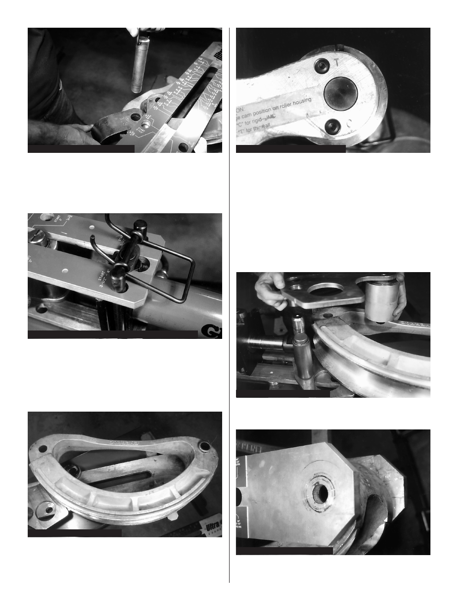
Figure 14: Installing “U” Strap & Pin
Figure 15: Model B400 & B400D Cylinder Block Locations
Figure 17: Position of Indicator Knob
Figure 18: Top Plate Installation
Figure 19: Bend Shoe Pivot Hole
Figure 16: Installing Bend Shoe
2. Slide the cylinder along the bottom frame until the
cylinder mounting block grooves are aligned with
the desired holes in the lower frame.
3. Position the bend shoe on top of the lower roller
plate. Be sure the bend angle numbers are
facing up. Figure 16.
4. The top plate and roller assembly are installed
over the bend shoe. Prior to installation, be sure
to move the indicator knob to either “C” for Rigid/
IMC or “T” for EMT (thinwall) conduit. Figure 17.
5. The axle for the large roller (upper plate
assembly) has two flats which engage the retainer
of the lower plate assembly. Press the upper roller
down until the lower roller axles are flush with the
top plate. The flats on the upper roller axle must
fully seat into the retainer collar. Figure 18.
NOTE: The roller assembly may not fully seat on the
first attempt. To ensure proper engagement,
move the indicator knob (slightly) until the
axles of the lower rollers are through the top
plate and flush with the top of it.
6. Move the bend shoe to align the pivot hole with
the hole at the end of the lower frame. Figure 19.
bend shoe. Install the retaining pin (BZ78) through
the upper frame, bend shoe, and lower frame.
Secure with hairpin cotter. Figure 20.