90° stub-up and kick bend instructions, Follow bar synchronization - removal, Procedure for removal – Gardner Bender B400 Series Eegor Hydraulic Benders User Manual
Page 10: Caution, Set-back chart
10
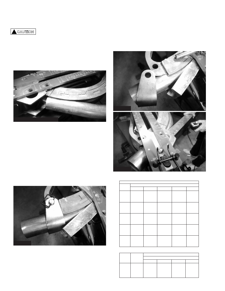
Figure 37
2. Once close to the follow bar, remove the U-strap by
pulling the pin. Figure 37.
3. Assist follow bar out by retracting the bend shoe
further while pulling out the follow bar with your
free hand. Figure 38.
4. For standard Eegor
®
models, the double pin will
always end in the same frame holes it started in.
90° Stub-up and Kick Bend Instructions
Set-back Chart
Diagonal Distance (D) Chart
Rise
Bend Angle
(H)
15°
30°
45°
60°
90°
2
7
3
⁄
4
4
2
13
⁄
16
2
5
⁄
16
2
4
15
7
⁄
16
8
5
11
⁄
16
4
5
⁄
8
4
6
23
3
⁄
16
12
8
1
⁄
2
6
15
⁄
16
6
8
30
15
⁄
16
16
11
5
⁄
16
9
1
⁄
4
8
10
38
5
⁄
8
20
14
1
⁄
8
11
9
⁄
16
10
12
46
3
⁄
8
24
17
13
7
⁄
8
12
14
54
1
⁄
16
28
19
13
⁄
16
16
3
⁄
16
14
16
61
13
⁄
16
32
22
5
⁄
8
18
1
⁄
2
16
18
69
9
⁄
16
36
25
7
⁄
16
20
13
⁄
16
18
20
77
1
⁄
4
40
28
5
⁄
16
23
1
⁄
8
20
22
85
44
31
1
⁄
8
25
3
⁄
8
22
24
92
3
⁄
4
48
33
15
⁄
16
27
11
⁄
16
24
26
100
7
⁄
16
52
36
3
⁄
4
30
26
28
108
3
⁄
16
56
39
5
⁄
8
32
5
⁄
16
28
30
115
15
⁄
16
60
42
7
⁄
16
34
5
⁄
8
30
Nominal
“S” Set-back Dimension (inches)
Conduit Stub-ups
Kick Bends
Size
90°
60°
45°
30°
15°
2
1
⁄
2
15
5
⁄
8
9
1
⁄
8
6
3
3
⁄
8
1
5
⁄
8
3
18
3
⁄
4
11
7
1
⁄
8
4
1
3
⁄
4
3
1
⁄
2
24
13
3
⁄
4
8
7
⁄
8
4
7
⁄
8
1
7
⁄
8
4
28
16
1
⁄
4
10
3
⁄
8
5
1
⁄
2
1
7
⁄
8
10. To remove bent conduit, press the “Retract” button
and hold it until the conduit returns to the starting
position.
When the conduit returns to the
starting position, the conduit and
follow bar become loose enough to fall
out of the bender. Grab the follow bar
to prevent it from falling out of the
roller assembly.
11. Remove the follow bar, then remove the bent
conduit from the roller assembly. Turn pump off.
!
CAUTION
Follow Bar
Synchronization - Removal
Occasionally your follow bar may become out of
synchronization with the movement of the bend shoe
on the return cycle.
If this happens, care should be taken by visual
inspection as you are retracting the cylinder. Figure 36
illustrates what to look for in an out-of-phase
condition. You will note the follow bar slipped forward
over the strap, rather than the front end of follow bar
remaining behind the strap.
Procedure for Removal
1. After completing desired bend, retract the bend
shoe until the strap is
close to the follow bar as
shown in figure 36. Do not retract further or make
contact with the U-strap against the follow bar or
breakage could occur.
Figure 38
Figure 36
Figure 35: Removing Conduit