Caution – Gardner Bender HYDRAULIC HAND PUMPS AND CYLINDERS User Manual
Page 4
WARRANTY: GB ELECTRICAL, INC. warrants its
products against defects in workmanship and
materials for 1 year from date of delivery to user.
Chain is not warranted. Warranty does not cover
ordinary wear and tear, abuse, misuse, overloading,
altered products or use of improper fluid.
WARRANTY RETURN PROCEDURE: When
question of warranty claim arises, send the unit to the
nearest GB Authorized Service Center for inspection,
transportation prepaid. Furnish evidence of purchase
date. If the claim comes under the terms of our
warranty the Authorized Service Center will REPAIR
OR REPLACE PARTS AFFECTED and return the unit
prepaid.
PARTS AND SERVICE: For quality workmanship and
genuine GB ELECTRICAL parts, select an Authorized
GB Service Center for your repair needs. Only
repairs performed by an Authorized Service Center
displaying the official GB Authorized sign are backed
with full factory warranty. Contact GB Electrical
(414) 352-4160 for the name of the nearest GB
Authorized Service Center.
REPAIR AND SERVICE INSTRUCTIONS: For repair service and parts contact your nearest GB ELECTRICAL
Service Center. The Service Center will provide complete and prompt service on all GB ELECTRICAL products.
GB Electrical, Inc.
An Applied Power Company
6101 N. Baker Road, Milwaukee, WI 53209
Phone: (414) 352-4160
FAX (414) 352-2377
RPS-0070 Rev. A
03/07
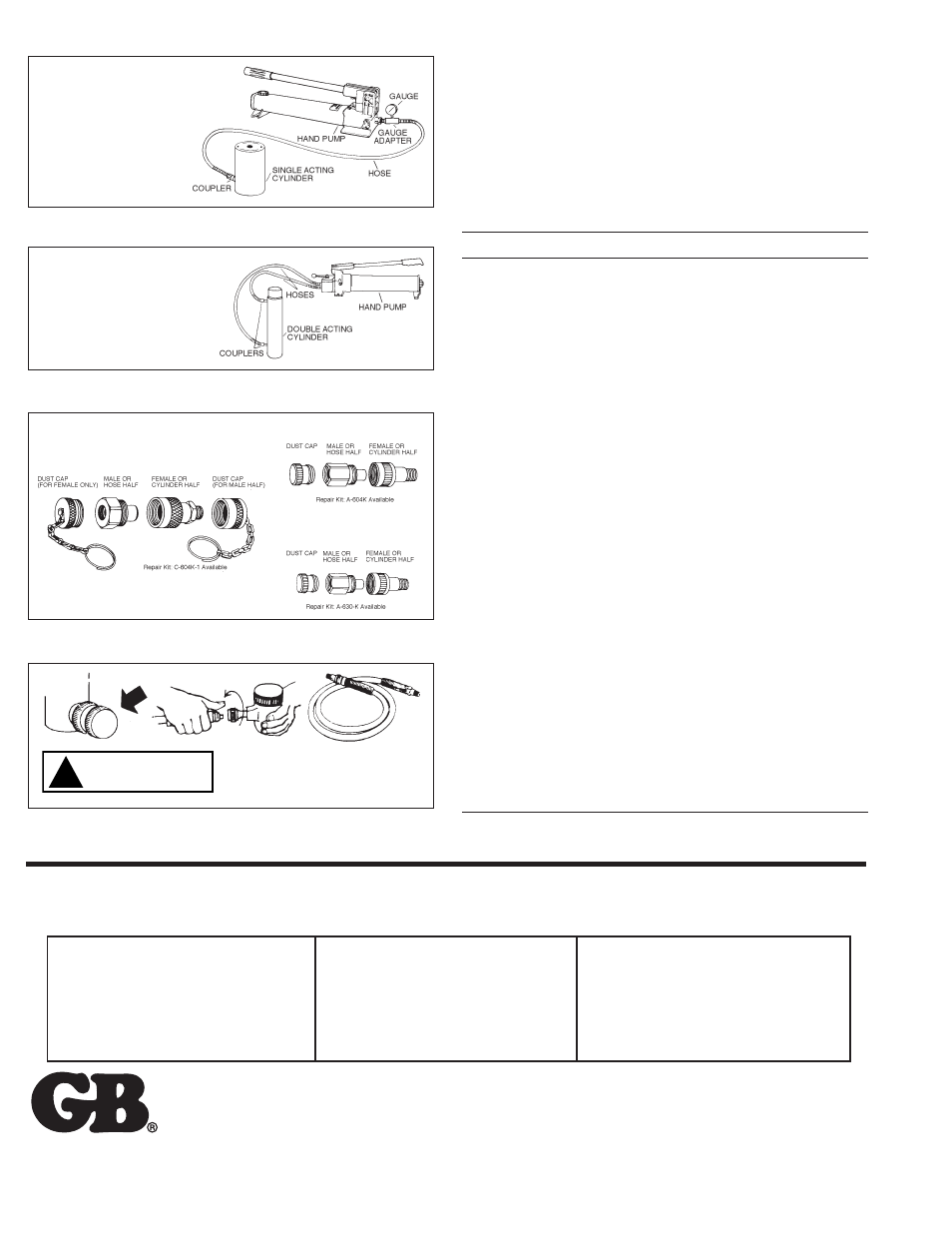
Figure 13
Connecting a Single-Acting Cylinder to a Hand Pump
Figure 14
Connecting a Double-Acting Cylinder to a Hand Pump
Figure 15
Couplers
Figure 16
Keeping Oil Lines Clean
TROUBLESHOOTING
1. Advance the hydraulic cylinder into its fullest extension. If the cylinder
does not fully advance, refer to Problems No. 1 and 2 below.
2. After the cylinder is advanced, continue to pump until the gauge shows
approximately 3,000 PSI of hydraulic pressure. If 3,000 PSI cannot be
obtained, refer to Problem No. 5 below.
3. After 3,000 PSI is obtained, put your hydraulic system into the hold
position. If the pressure drops rapidly, refer to Problem No. 5 below.
PROBLEM
POSSIBLE CAUSE
1.
Cylinder will not
A. Pump release valve open
advance
B. No oil in pump
C. Air bound
D. Couplers not fully tightened
E. Blocked hydraulic line
F. Pump not operating
2.
Cylinder advances
A. Oil level in pump is low
part way.
B. Cylinder plunger binding
C. Air trapped in cylinder
3.
Cylinder advances
A. Air in hydraulic system
in spurts
B. Cylinder plunger binding
4.
Cylinder advances
A. Leaking connection
slower than normal
B. Restricted hydraulic line or fitting
C. Loose coupler
D. Pump malfunctioning
5.
Cylinder advances
A. Cylinder seals leaking
but will not hold
B. Leaking connection
pressure
C. Pump malfunctioning
D. Incorrect system set-up
6.
Cylinder leaks oil
A. Worn or damaged seals
B. Loose connection
C. Internal cylinder damage
7.
Cylinder will not
A. Pump release closed
retract or retracts
B. Coupler not fully closed
slower than normal
C. Blocked hydraulic line
D. Broken retraction spring
E. Pump reservoir over-filled
F. Cylinder damaged internally
8.
Cylinder will not
A. Weak retraction spring
fully retract
B. Pump reservoir over-filled
C. Partially blocked hydraulic line
D. Damaged internally or externally
Hand Pump – Two-way Release Valve
Hose – One required
Coupler – Male half coupler on hose
Single-Acting Cylinder – Hydraulic
force in one direction only. Female
half coupler on cylinder.
Hand Pump – Four-Way Valve
(Pump Mounted)
Hose – Two required
Coupler – Male half coupler on each hose
Double-Acting Cylinder – Hydraulic force
in advance and retract. Two female half
couplers on cylinder.
3
/
8
" HIGH FLOW COUPLER
3
/
8
" REGULAR COUPLER
1
/
4
" COUPLER
Dirt and foreign matter may cause pump, cylinder,
or valve failure. Use every precaution to guard
against entrance of dirt. When coupler halves are
disconnected, always screw on dust caps.
!
CAUTION