Burkert Type 1094 User Manual
Page 4
4
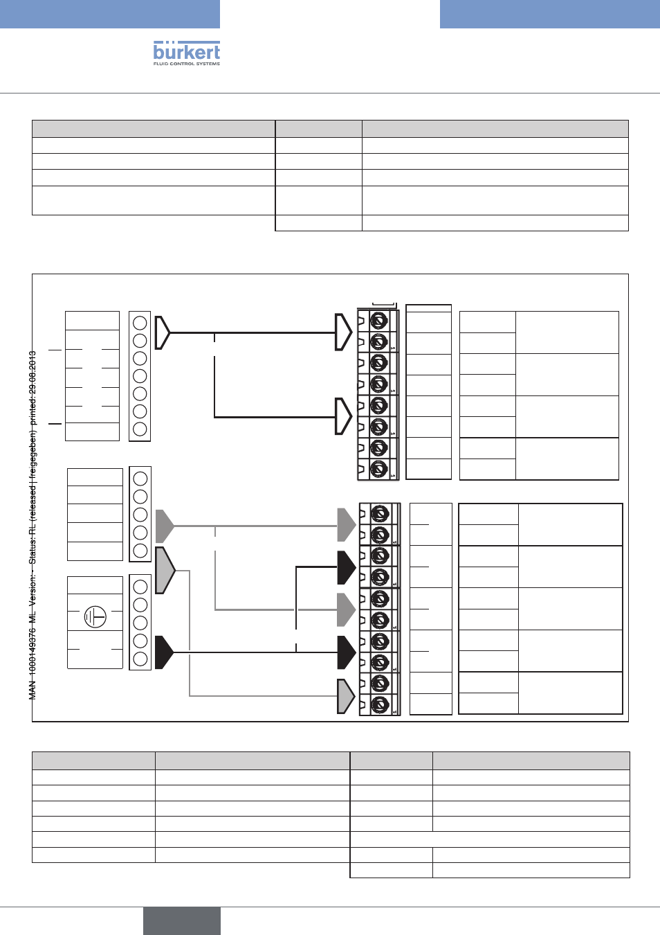
Information on the replacement
of the electronic control
Pin assignment (old)
Labeling
Pin assignment (new)
Valve A (+ and –)
→ Ventil 1
Control of valve, side 1
Control of pump B (+ and –)
→ Schütz 2
Control of motor contactor, side 2
Control of pump A (+ and –)
→ Schütz 1
Control of motor contactor, side 1
Operating voltage (230 V or 115 V)
→ -
No longer required. Power supply unit operates at
voltages from 100 V AC to 240 V AC
Also: Diesel 1 / 2
Diesel identifier side 1 and side 2
Pin assignment for replacement of the ident. no. 60651
0 V
1
2
3
4
5
12 V out
Eingang / Input
12 V in
Alarm out
Pumpe out
24 V out
24 V –
0 V
+
–
Ventil
Valve
GND
Diesel 2
GND
Impuls 2
GND
Diesel 1
GND
Impuls 1
+ Input
Frequency input
Gasoline pulse
Side 1
GND
+ Input
Diesel identifier
Side 1
GND
+ Input
Frequency input
Gasoline pulse
Side 2
GND
+ Input
Diesel identifier
Side 2
GND
Inputs
is replaced by ident. no. 208373
Inputs
or *
* leave other side
open
+ 24V
GND
+
–
+
–
+
–
+
–
Ventil 1
Schütz 1
Ventil 2
Schütz 2
GND
Motor contactor
control
Side 2
+ Output
GND
Valve control
Side 2
+ Output
GND
Motor contactor
control
Side 1
+ Output
GND
Valve control
Side 1
+ Output
GND
24 V supply
+ Output
Outputs
Outputs
or *
or *
Old ident. no. 60651
not used
not
used
Overview of assignment: Old → New
Labeling
Pin assignment (old)
Labeling
Pin assignment (new)
Input 0 V / 1
Input GND and 1
→ Impuls1 / 2
Frequency input side 1 or 2
12 V out / 12 V in
-
No longer available
Pumpe out / 24 V out
Control of pump
→ Schütz 1 / 2
Control of motor contactor side 1 or 2
Output 24 V – / 0 V
Operating voltage GND / + 24 V
→ GND / + 24 V 24 V supply
Symb. for prot. conductor Protective conductor
→ No longer available/required
Ventil / Valve + /–
Valve (+ and –)
→ Ventil 1 / 2
Control of valve side 1 or 2
also Diesel 1 / 2
Diesel identifier sides 1 and 2
english
Type 1094