Appendix b: device cabling – Avocent CCM1640 User Manual
Page 92
86
CCM840/1640 Installer/User Guide
Appendix B: Device Cabling
Each CCM serial port has an RJ-45 connector for attaching a serial device. The
following table lists the pin assignments.
Port Pin Assignments
Pin #
RS-232 Signal
Direction
Description
1 RTS Output
Request
To
Send
2
DSR
Input
Data Set Ready
3
DCD
Input
Data Carrier Detect
4 RxD Input Receive
Data
5 TxD
Output
Transmit
Data
6 GND (N/A) Signal
Ground
7 DTR Output
Data
Terminal
Ready
8
CTS
Input
Clear to Send
NOTE: RI (Ring Indicate) is not supported
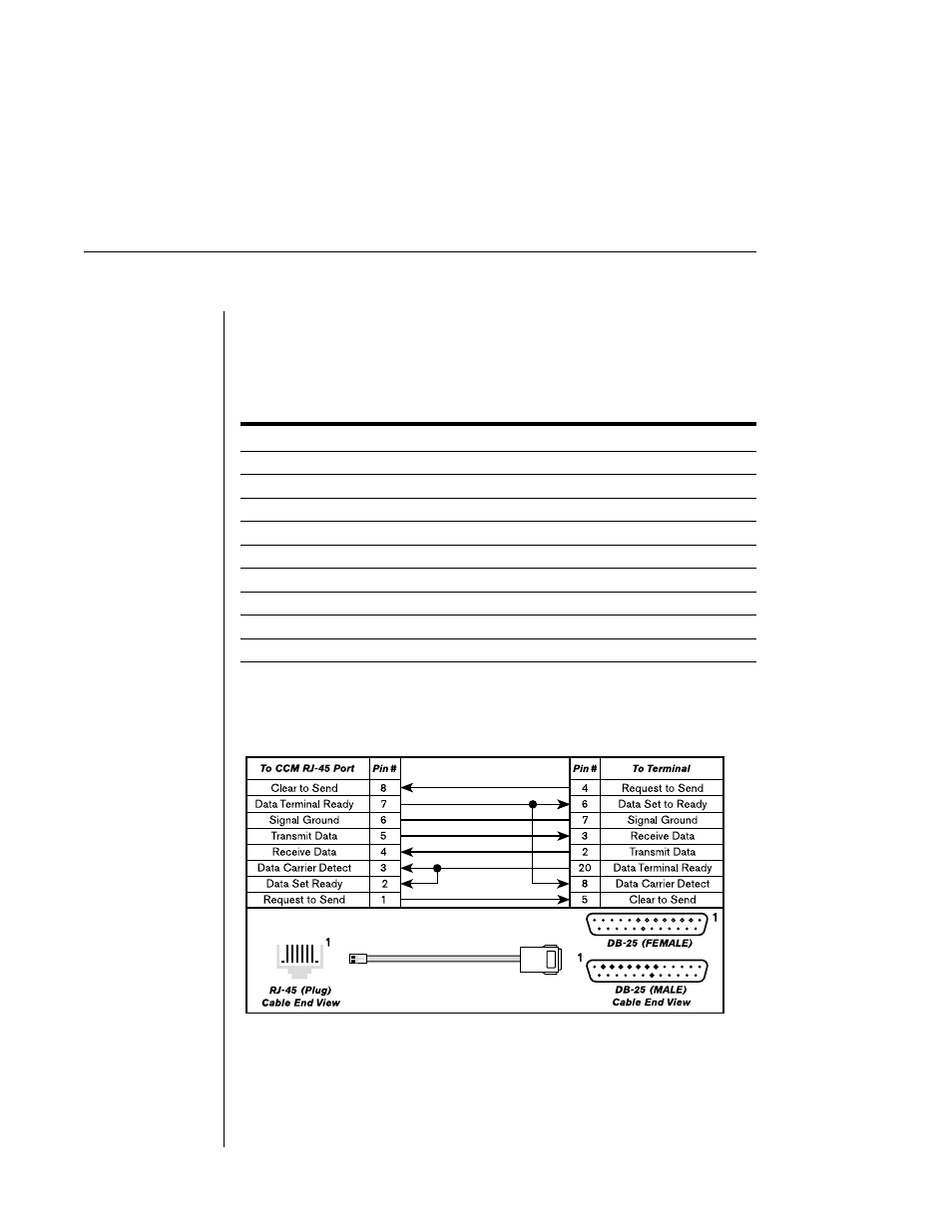
Figures B.1 through B.3 show the wiring diagrams for cables that connect from
CCM ports to terminals/printers, PCs and modems.
Figure B.1: Cable Pin Assignments for RJ-45 to Terminal/Printer
This manual is related to the following products: