Caution, Model 1358 – Brooks Instrument 1358 User Manual
Page 16
Installation and Operation Manual
X-VA-1358-eng
Part Number: 541B041AAG
September, 2012
3-2
Section 3 Operation
Model 1358
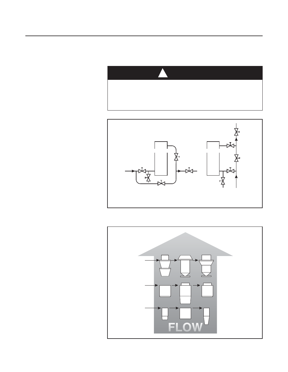
Rate of flow is indicated by reading the increments inscribed on the
metering tube or direct etched scale parallel with the metering edge of the
float. For the correct reading edge of the float, refer to Figure 3-2.
CAUTION
!
A built-in needle control valve may be provided to control the flow
through the flowmeter. These control valves are designed for fine
control. Excessive tightening may damage the valve seat and limit its
effectiveness as a control valve. If tight shut-off is required, it is
recommended that a separate shut-off valve be installed in the line
immediately before the flowmeter.
Figure 3-1 Typical Bypass Installation
A - Inlet Valve
B - Outlet Valve
C - Bypass Valve
D - Control Valve
E - Drain Valve
HORIZONTAL
LINE
D
A
E
C
VERTICAL
LINE
B
B
A
E
FLOWMETER
C
D
FLOWMETER
Figure 3-2 Reading Edge of floats
READ
HERE
READ
HERE
READ
HERE
LJ
RV
RS
RJ
RJ
RJ
RJ
RJ
RJ