Brooks, Digital mfc's and mfm's – Brooks Instrument SLAMf Series User Manual
Page 52
4-4
Section 4 Maintenance &
Troubleshooting
Installation and Operation Manual
X-TMF-SLAMf-MFC-eng
Part Number: 541B032AAG
April, 2013
Brooks
®
Digital MFC's and MFM's
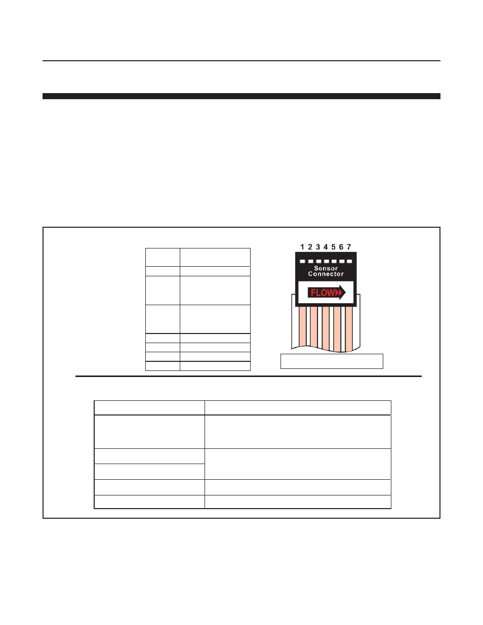
Remove the sensor connector from the PC Board for this procedure.
OHMMETER CONNECTION
RESULT IF ELECTRICALLY FUNCTIONAL
Open circuit on ohmmeter. If either heater (1) or
Pin 1 or 4 to meter body
sensor common (4) are shorted, an ohmmeter
reading will be obtained.
Pin 4 to Pin 2
Nominal 1100 ohms reading, depending on
Pin 4 to Pin 3
Pin 5 to Pin 1
Nominal 1000 ohm reading.
Pin 6 to Pin 7
Nominal 580 ohm reading.
temperature and ohmmeter current.
SENSOR
SCHEMATIC
PIN
NO.
FUNCTION
1
Heater
Upstream
2
Temperature
Sensor (Su)
Downstream
3
Temperature
Sensor (Sd)
4
Sensor Common
5
Heater Common
6
Thermistor
7
Thermistor
Table 4-1 Sensor Troubleshooting
Flex Circuit Wire Numbers
4-1-3 Calibration Procedure
The calibration of Brooks Digital Series Mass Flow devices is not described
in this manual. Such calibration requires accurate and traceable calibration
equipment in addition to digital communications.
If your device needs calibration Brooks Instrument can provide this service
at one of its service locations. Visit www.BrooksInstrument.com to locate
the service location nearest to you. However, if traceable calibration
equipment is available at your facility, Brooks service Suite Calibration
software, along with training, is available for purchase.