Brooks, Digital mfc's and mfm's – Brooks Instrument SLAMf Series User Manual
Page 43
3-9
Section 3 Operation
Installation and Operation Manual
X-TMF-SLAMf-MFC-eng
Part Number: 541B032AAG
April, 2013
Brooks
®
Digital MFC's and MFM's
Diagnostic
Failure Description
RAM
Byte by byte test of RAM detects bad memory location
Flash (Program Memory)
8-bit Checksum of the entire Flash not zero.
Non-Volatile Memory
Byte by byte test of Non-Volatile Memory detects bad memory
location
Temperature Sensor
Temperature Sensor reports a value outside the designed range of
0° C to 100° C
Power Supply (Internal)
Any internally generated power supply voltage outside operational
limits. (3.3 Volt and 7.6 Volt internal supply voltages must be within
±5% of nominal value.)
Alarm
Severity
Alarm
Latching Contact Low
High
Delay
Code
Enable
Enable
Limit
Limit
Diagnostic
Alarm
12
n/a
Off
n/a
n/a
n/a
Flow 1
Off
11
Off
Off
0%
120%
1.0
Flow 2
Off
10
Off
Off
0%
120%
1.0
No Flow Indication
Alarm
9
Off
Off
2%
n/a
1.0
Setpoint Deviation
Alarm
8
Off
Off
-10%
+10%
1.0
Totalizer Overflow
Off
7
n/a
Off
n/a
n/a
n/a
User Power Supply
Alarm
6
Off
Off
13.5
27.0
1.0
Setpoint Input Out of Range
Alarm
5
Off
Off
n/a
n/a
1.0
Flow Output Out of Range
Alarm
4
Off
Off
n/a
n/a
1.0
Flow Output Loop Open
Off
3
Off
Off
n/a
n/a
1.0
Flow Sensor Out of Range
Alarm
1
Off
Off
n/a
n/a
1.0
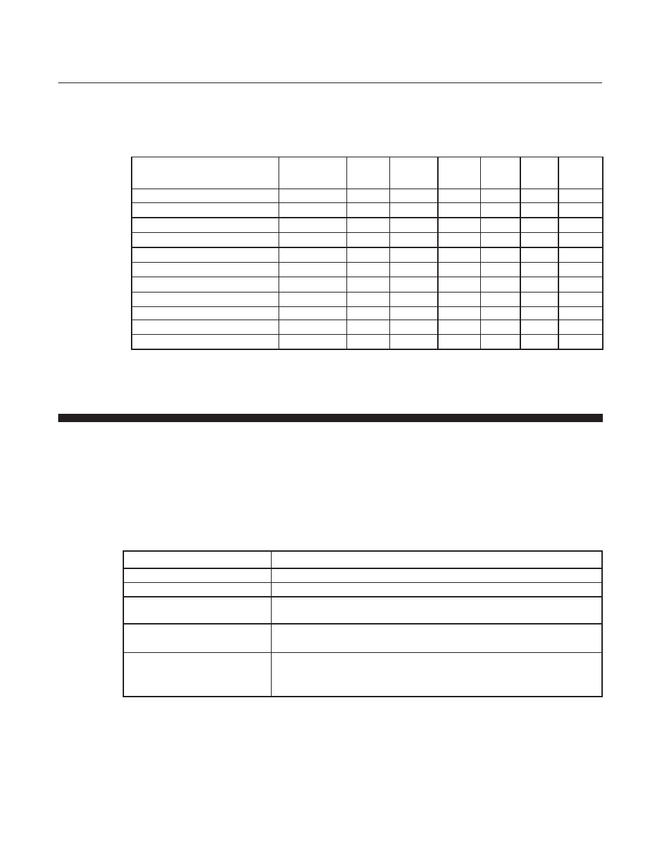
Alarm Summary
The following table summarizes the parameters for each alarm type and
the respective default values.
3-6-2 Diagnostic Alarms (Analog versions only)
A Diagnostic Alarm will be indicated when any of the diagnostics below
detect a failure providing a visual indication via the red and/or green LED,
and activating the TTL open collector output located on the 15 pin
D-Connector. The diagnostic test or tests that have detected a problem and
caused the Diagnostic Alarm to occur can be determined only by reading a
parameter via the Service Port. When a diagnostic alarm occurs, the
device will automatically reset after approximately 5 seconds.