Brooks, Digital mfc's and mfm's – Brooks Instrument SLAMf Series User Manual
Page 18
1-12
Section 1 - Introduction
Installation and Operation Manual
X-TMF-SLAMf-MFC-eng
Part Number: 541B032AAG
April, 2013
Brooks
®
Digital MFC's and MFM's
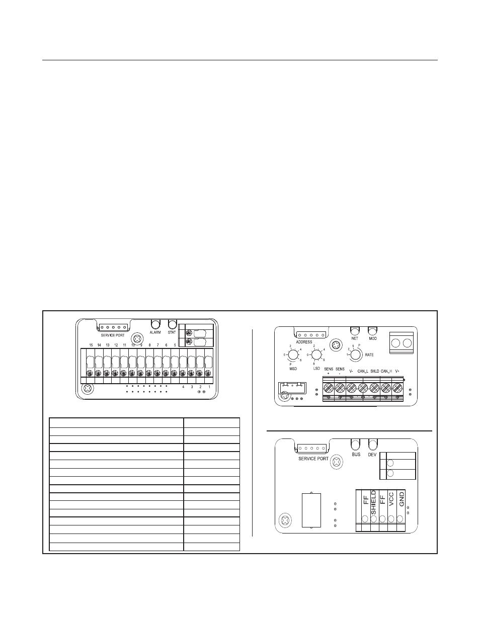
Figure 1-5 Analog, DeviceNet and F
OUNDATION
Fieldbus Terminal Layouts
Analog I/O Pin Function PIN
Setpoint, Command Input (-)
1
Flow Signal, 0(1) -5 volt, Output (+)
2
TTL Alarm, open collector, Output (+)
3
Flow Signal, 0(4)-20 mA, Output (+)
4
Power Supply, +13.5 Vdc to +27 Vdc(+)
5
Not Connected
6
Setpoint, 0(4)-20 mA, Input (+)
7
Setpoint, 0(1)-5 Vdc, Input (+)
8
Power Supply, Common (-)
9
Flow Signal, Common, Output, (-)
10
Reference, +5 Vdc, Output (+)
11
Valve Override, Input
12
Calibration Select Input
13
RS-485 Common B (-)
14
RS-485 Common A (+)
15
DeviceNet Terminal Layout
PC-based Support Tools
Brooks Instrument offers a variety of PC-based process control and service tools to meet the needs of our
customers. Smart DDE may be used with any unit supporting RS-485 in a multidrop configuration, thus allowing
users to control and monitor their Brooks devices. The Brooks Service Tool
TM
(BST) may be used to monitor,
diagnose, tune and calibrate Brooks devices equipped with DeviceNet or F
OUNDATION
Fieldbus communications.
The Brooks Service Tool
TM
interfaces with Brooks products via a special service port.
F
OUNDATION
Fieldbus Terminal Layout
Analog Terminal Layout