Brooks, Model 5860 i – Brooks Instrument 5860i User Manual
Page 16
2-6
Brooks
®
Model 5860
i
Section 2 Installation
Installation and Operation Manual
X-TMF-5860i-MFM-eng
Part Number: 541B110AAG
November, 2008
2-8 Configuring the PC Board
NOTE: To obtain access to the jumpers, the electronics cover must be
removed. Disconnect the power to the mass flow meter, and cables to the
D-connector. Remove the three screws at the base of the can and remove
the top jack post of the D-connector. Remove the can. The can must be
replaced before returning the unit to service.
Refer to Section 2-6 for the proper electrical hook-up. Refer to Figure 3-5
for printed circuit board jumper locations and functions.
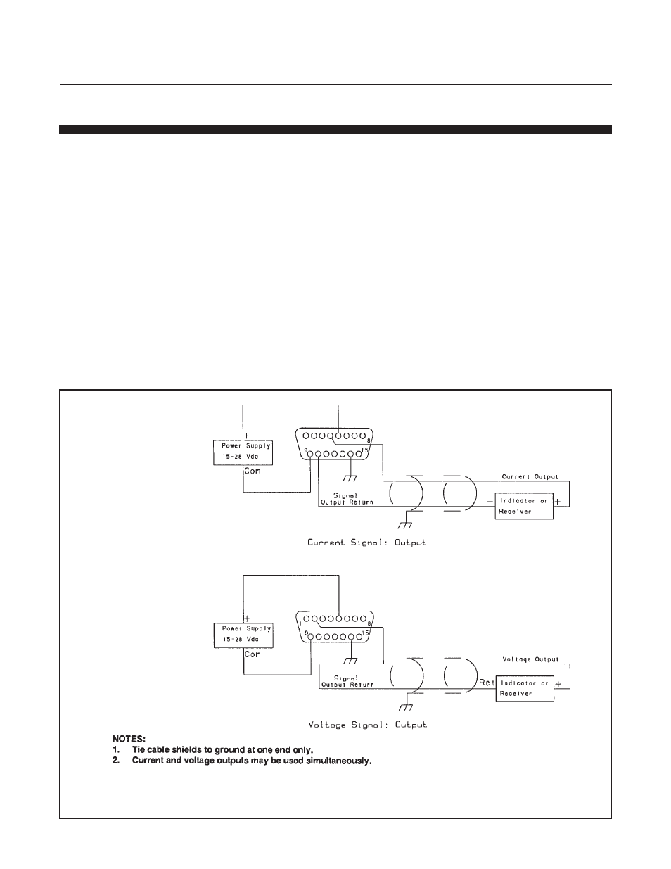
Signal Output
A 0-5 Vdc flow signal is always available. The current signal output is
jumper-selectable for either 0-20 mAdc or 4-20 mAdc. Jumpers J3 and J4
( blue ) must be in the upper position for 0-20 mAdc output and in the lower
position for 4-20 mAdc output.
NOTE: Both J3 and J4 must be in the same position. Jumpers J3 and J4
do not affect the voltage output.
Figure 2-4 Common Electrical Hook-Ups