Manta input block diagram, Manta delay and minimum pulse width, Test conditions – ALLIED Vision Technologies Manta G-917 User Manual
Page 107
Manta Technical Manual V7.0.1
107
Camera interfaces
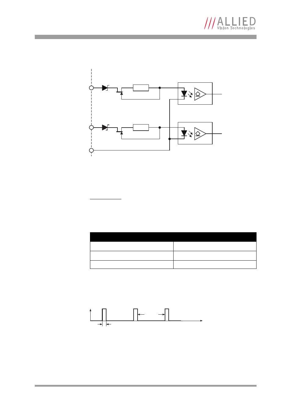
Manta input block diagram
The inputs can be connected directly to the system for voltages up to 24 V DC.
An external resistor is not necessary.
Manta delay and minimum pulse width
The minimum pulse width for all Manta cameras is:
Test conditions
The input signal was driven with 3.3 V and no external additional series resistor.
Figure 66: Manta input block diagram
Note
For customers who designed their system for Manta cameras
with serial numbers prior to the above mentioned hardware
change:
Use your systems with an external resistor without any
restrictions.
Parameter
Value
U
in
(low)
0–1.0 V
U
in
(high)
3–24 V
Current (constant-current source)
3–4 mA
Table 32: Manta input parameters
Figure 67: Manta minimum pulse width
GPIn1
InGND
External Internal
GPIn2
180R
180R
I
F
0
t
44 μs
6 μs
20 kHz