Installation process, Step one – pre-plan controller network – Contemporary Research SW-DX Integration Guide User Manual
Page 2
Contemporary Research
2
iC-Net Tips – RF Design and Installation
Display Control Software
There are several ways that CR display networks can be controlled:
Display Express software connected to an ICC-HE Head End. The Web-based control
software can be accessed anywhere on a network, usually located adjacent to Head
End.
SignStream Media Player connected to the ICC-HE Head End via RS-232 (It’s usually
in the same rack as the Head End)
Custom software, running on an AMX, Crestron, or other control system, often
connected to an ICE-HE Ethernet Head End over a network.
Installation Process
In most systems, one group of installers will integrate the displays, then another tech
comes in after that to install and test Display Express software or a custom control system.
The following installation process will allow the first team to correctly install the displays and
verify the install long before the control software is integrated.
Step One
– Pre-Plan Controller Network.
Display Controllers are identified on the RF network by unique addresses. There are 4,000
possible addresses, divided into 15 zones. All the controllers within the same zone respond
immediately to a single zone command. Some systems use a simple architecture, using the
same address for all controllers in the same zone. As control for specific controllers may be
needed in the future, it’s usually a good practice to assign each a unique address.
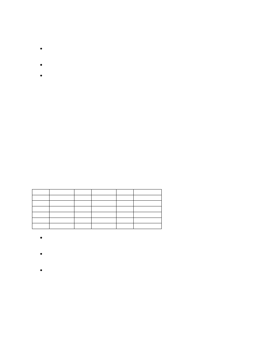
Zones
Zone Address Zone Address Zone Address
1
256
6
1536
11
2816
2
512
7
1792
12
3072
3
768
8
2048
13
3328
4
1024
9
2304
14
3584
5
1280
10
2560
15
3840
All
4095
In most systems, try to arrange the addresses to fit into the natural Zones in the
network. This way, most commands affect all displays in each Zone with a single
command.
The new Display Express software, versions 4.3 and above, can also create free-form
Groups. This is useful for controlling a set of displays that don’t fit the normal Zone
structure.
Set up a spreadsheet that defines all the displays in the system, include the name,
location and network address. This becomes a “roadmap” for the team that installs
the displays.
From the Roadmap, go ahead and set the addresses and label the display controllers. This
simplifies the job for the team that installs the displays, and reduces system installation
errors.