Tools required for installation parts – CHIEF KWT110 User Manual
Page 7
Installation Instructions
KWT-110
7
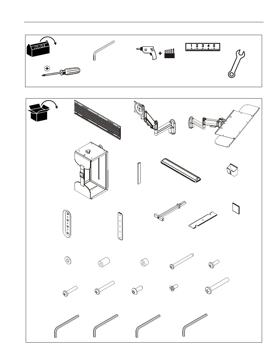
TOOLS REQUIRED FOR INSTALLATION
PARTS
7/64"
#2
17/64"
1/2"
3/32" (included)
1/8" (included)
3/16" (included)
5/32" (included)
7/16"
A (1)
[Wall track accessory]
B (1)
[Centris display mount]
C (1)
[Keyboard tray mount]
D (1)
[CPU mount]
E (4)
[3" rubber edging]
F (1)
[Gel wrist pad]
G (1)
[Mouse holder]
H (2)
[Wall plate]
J (2)
[Locking plate bracket]
K (8)
1/4-20"
L (2)
[Cable management cover]
M (6)
[Hook and loop
fastener]
N (6)
#10
P (4)
.50 x .194 x .75
Q (4)
.50 x .194 x .375
R (6)
#12 x 2-1/2"
S (4)
M4 x 12mm
T (4)
M4 x 20mm
U (4)
M4 x 30mm
V (6)
#10-24 x 1/2"
W (4)
#8-32 x 3/8"
X (8)
1/4-20 x 1-3/4"
Y (1)
3/32"
Z (1)
3/16"
AA (1)
5/32"
BB (1)
1/8"